Balsa M2-F3 Lifting Body
Laser
In a previous post I talked about a laser-cut balsa model I built of a fictional spaceship from the movie “2001: A Space Odyssey”. Around the same time (early 2025) I was also motivated to try my hand at designing the parts, laser-cutting and building a scale replica of the real (not fictional) M2-F3 lifting body.
The laser I used, as I mentioned, is an entry-level Chinese CO2 laser. If you do a search on eBay for a "K40 Laser" you’ll find several. They might run from $300 to $500. I looked for one with air assist because I understand they improve cutting of some materials—I think wood might be one they are especially helpful for.
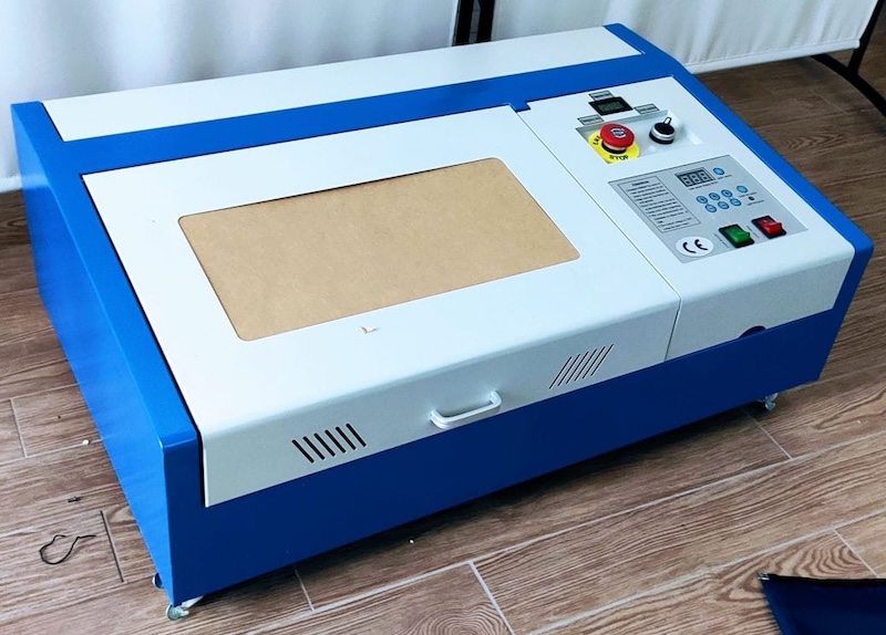
I bought a cheap mini PC from Amazon (maybe about $100) to be my dedicated driver for the device. I envisioned the laser living out in the garage on a table with a PC and monitor next to it. Sometimes it makes sense to have a dedicated machine that will not be subjected to arbitrary software updates, etc.—just live to serve one purpose.
Lifting Bodies
Perhaps I should step back and mention what a “lifting body” aircraft is. (In case you are unfamiliar.)
In the wild, earlier frontier of manned, space exploration, NASA (the National Aeronautics and Space Administration) was flush with ideas for future spacecraft. One of those involved building spacecraft that would land back on Earth like an airplane. At the time, astronauts returned in capsules that were carried down to Earth by parachutes—touching down within a fairly large area of uncertainty. Something “flyable” could land on a runway like other ordinary aircraft.
Since a high speed reentry from space involves a tremendous amount of friction heat, mounting wings on the returning spacecraft was always thought to be out of the question. A handful of aeronautical engineers though began to consider a new kind of stubby aircraft/spacecraft that did not have what we typically think of as wings. They imagined that the aerodynamic lift needed for the craft to glide could come from the shape of the body or fuselage itself.
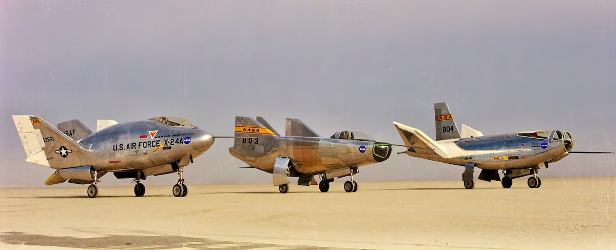
A series of designs were considered and eventually built. In typical experimental aircraft fashion they had evocative names like the M2-F1, the HL-10, the X-24A…
M2 Series
I’ll talk a bit more about the M2 aircraft in particular.
The M2-F1 was the vehicle that kicked everything off. Called the “flying bathtub”, the fuselage was primarily made from plywood over a steel frame. Testing if the vehicle could glide was done by towing it from behind a hot-rodded Cadillac across a dry, desert lakebed. Later tests had the craft towed into the air by a larger aircraft—and then released.
The performance was encouraging and a proper aluminum test aircraft was budgeted for and contracted out to a professional aircraft company. This new craft was designated the M2-F2. Infamously, it crashed on one of its test flights, the footage of which was replayed weekly in the opening credits of the 1970’s TV show The Six-Million Dollar Man.
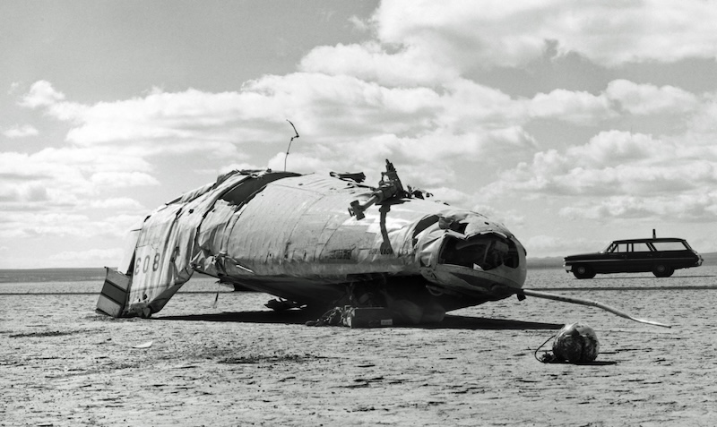
The test pilot fortunately survived (although he lost his sight in one eye). And as for the aircraft, like the titular character in The Six-Million Dollar Man, it was rebuilt.
It was determined that the crash had been caused by an aerodynamic instability in the design. The engineers found that a simple fix was to add a center fin between the two outboard ones that jutted up from the back of the aircraft. The addition of the center fin would isolate the wash from the roll control surfaces. It was this uncontrollable roll that had doomed the M2-F2.
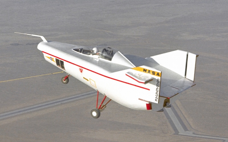
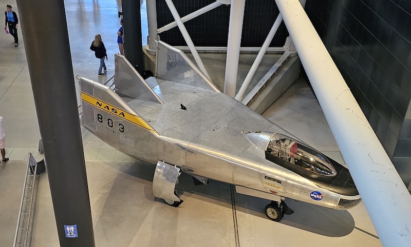
And so, with all the imagination you would expect, the new craft with the altered design was designated the M2-F3. (I like to think “F3” for “Fins 3”, but in fact it was merely the third iteration of the design.)
M2-F3
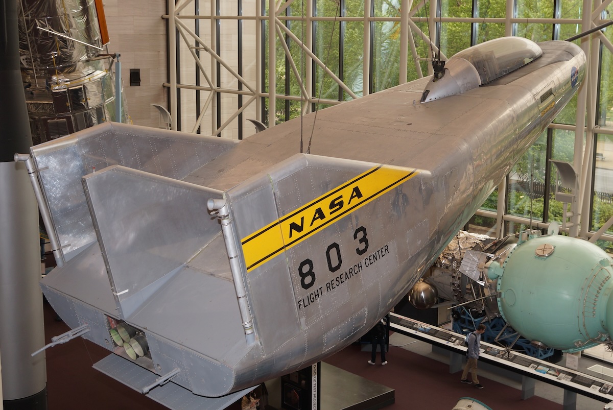
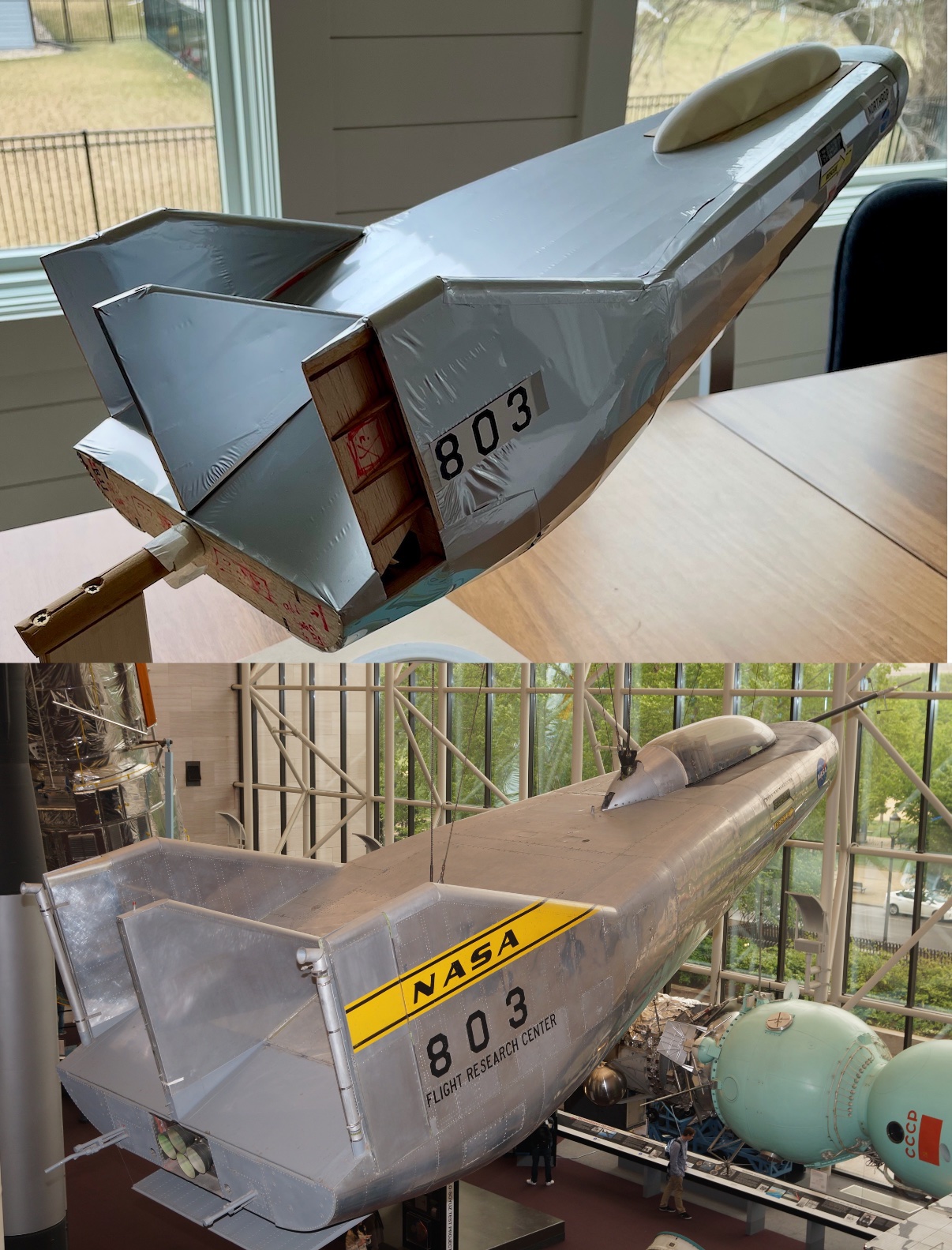
The M2-F3 flew well. It never made it into space but its successor (arguably) was the Space Shuttle (STS) which certainly did make it into space. The original M2-F3 is currently, as I understand it, on display at the National Air and Space Museum in Washington, D.C.
Iterations
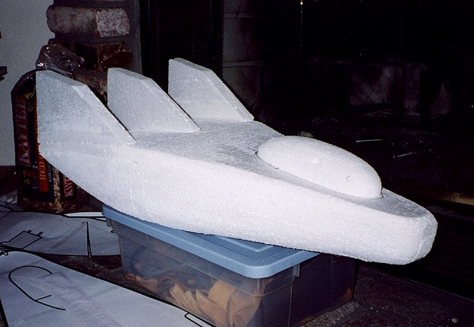
It’s such an unusual shape, I have wanted to build a model of one for many years now. My earliest iteration that I have a photo of was from perhaps 2002 or so—built up from styrofoam. I knew the fins were too fat for the scale, but back then (and at this early stage of messing around) I could overlook that.
I didn’t really go beyond what you see here. I think back then I was still trying to suss out the shape of the thing.
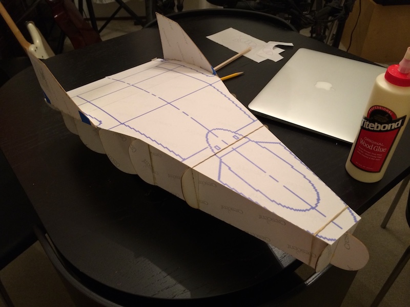
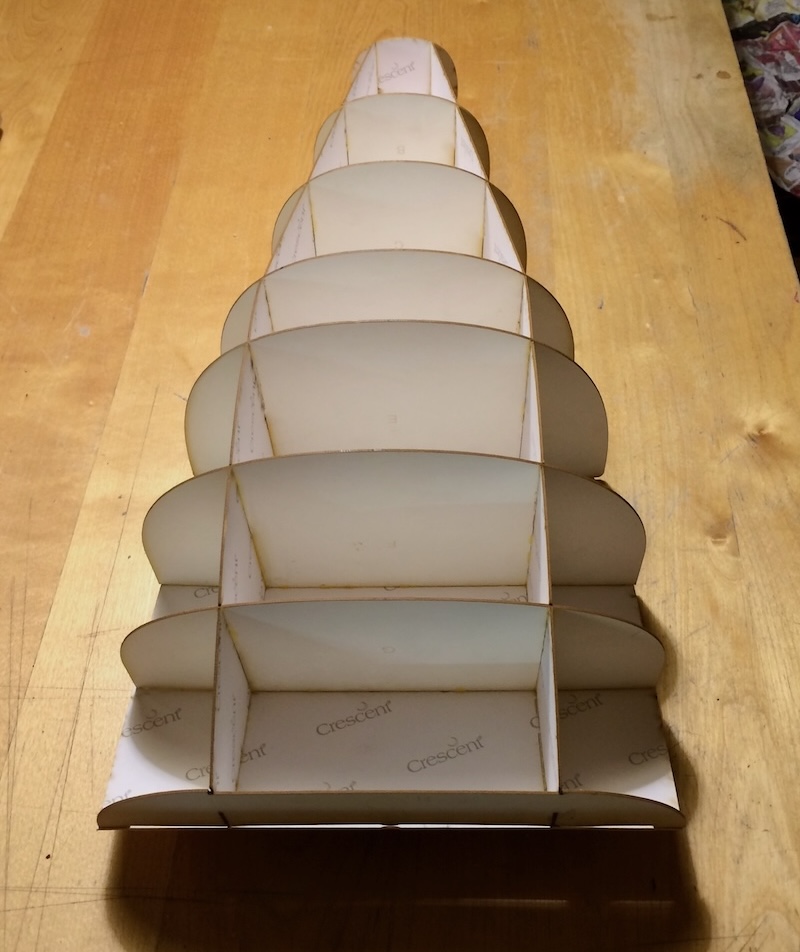
In 2014 I returned to the M2-F3—this time creating the form using cross-sections cut from heavy matte board. It looks like I had come across some new drawings of the M2-F3. I can see the internal structure made from the matte board is beginning to follow the internal structure of the actual aircraft. I really was trying to get the geometry as accurate as possible on new iterations.
It was becoming clear that the front half of the M2-F3 was essentially a split cone. In addition, rather than a pointed conical nose, the front was closer to hemispherical. Drawings I came across of the vehicle didn’t specify the tangle of the cone, the diameter of the hemisphere, etc. So I had to rely on measuring from photographs I could find of the aircraft—trying of course to find the perfect profile photo, perfect head-on photo, etc.
More complicated though was the boat tail of the M2-F3. What began as a conical shape transitioned at some point to a flat bottom. The roll-off of the leading edges of the fuselage tightened in radius and gave way to the vertical fins. The flat top deck began to slope downward until it met the blunt rear-surface.
Again, all the radii, station distances at which these transitions occurred were left a mystery. Building models out of foam and matte board allowed me to put down hard and fast curves and then, after construction, eyeball the result to see if it seemed to match what I was seeing in the photos.
At last I came across a document that described the geometry in more detail than I had previously known and the guesswork that had been required previously was reduced considerably.
Balsa
With the new document that gave me critical dimensions and with the success that I had found laser-cutting balsa (see my post about the balsa spaceship model from the movie: “2001”), the M2-F3 project was given a new lease.
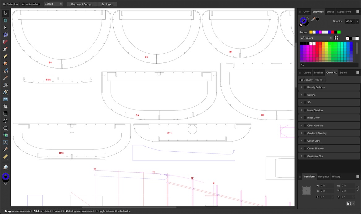
Also like the “2001” model, parts were designed vector-wise using the Affinity Designer app and then exported as PDF files. As I mentioned in the other post, the inexpensive laser limited me to a width of 12" of “laserable” area. Additionally, the sheets of balsa are often only 4" wide, limiting me finally to 12" by 4". To that end, some of the larger rib sections had to be sectioned themselves.
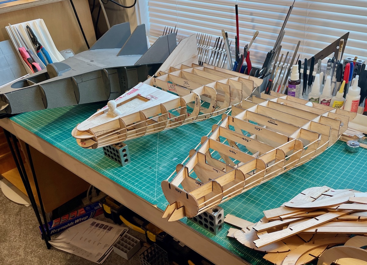
I staged the above photo to show an earlier Depron™ model (a kind of foam the model airplane community like to build with) that I had built earlier (the grey model on the far left) followed by two iterations in balsa.
Finally, you can see a stack of various balsa parts that may or may not have made the cut.
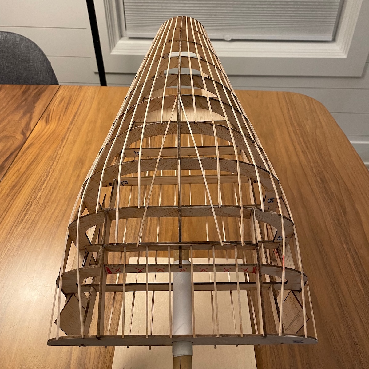
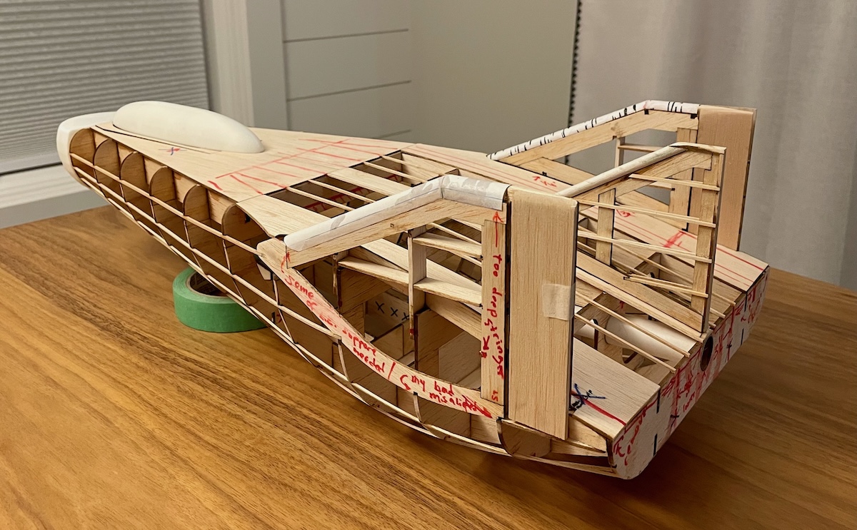
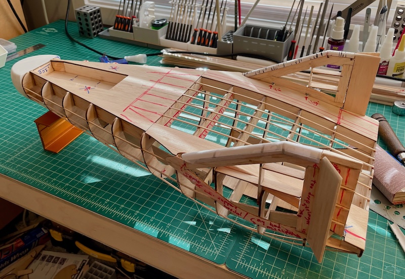
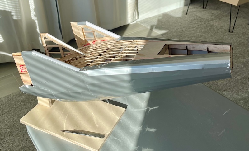
The stringers (also called longerons) are the thin strips of wood that run from the nose to the tail of the aircraft. When these started to be added, the shape of the aircraft really began to stand out.
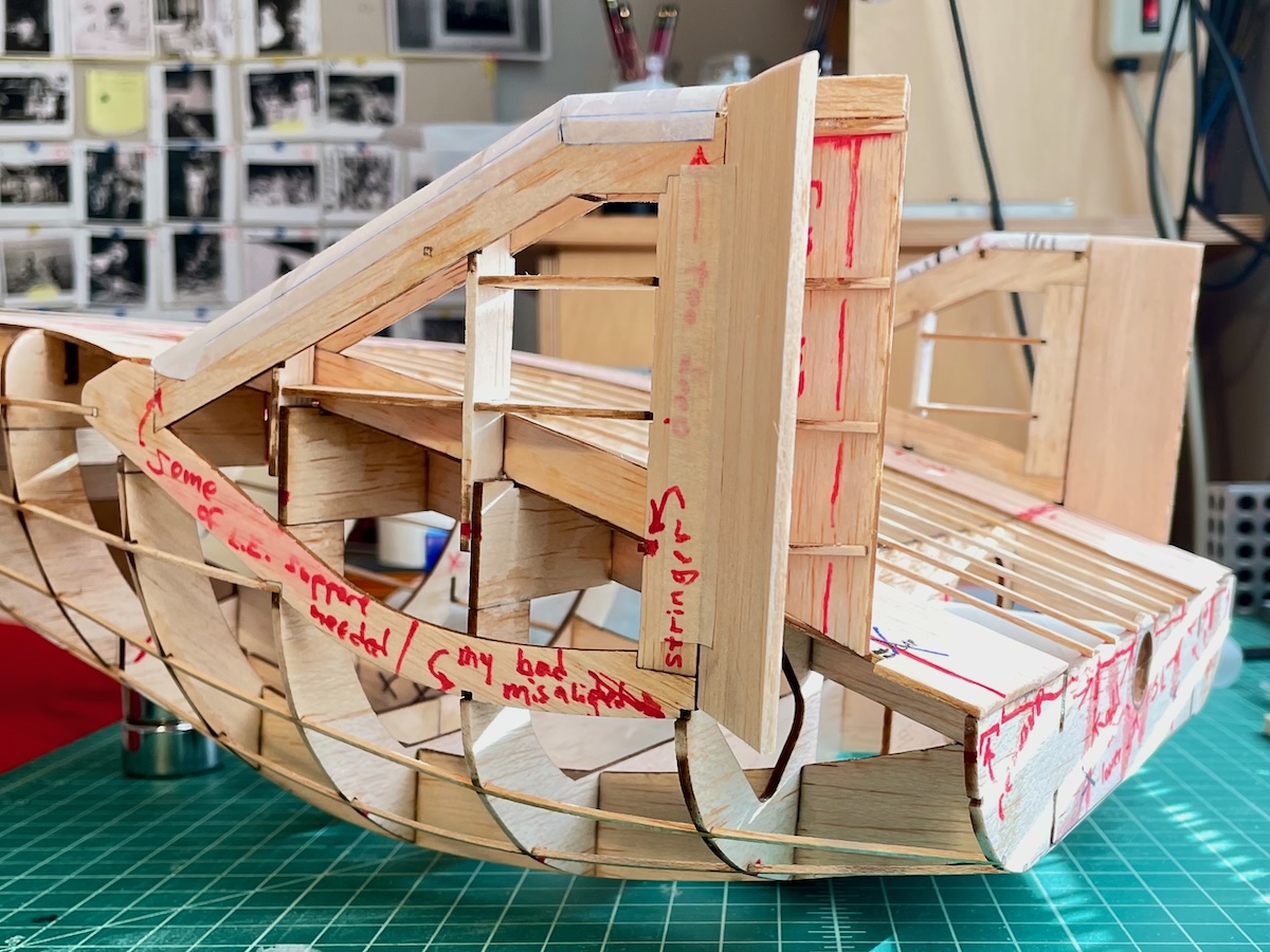
The tail is clearly the most complex geometry of the M2-F3. The above photo makes obvious my little annotations that I draw directly onto the model.
My M2-F3 model is indeed supposed to ultimately fly. To that end there is a cardboard tube in the rear suitable for a standard hobbyist rocket motor. Although the experimental aircraft was carried aloft under the wing of a B-52 and then dropped, the M2-F3 did have rocket motors in the rear to allow it to climb some distance after release and to extend it’s landing profile should it come up short of the designated runway.
Some of the last iterations were in order to add the control surfaces to the rear. The two outboard vertical fins have vertical flaps to give it some yaw capability. The upper rear deck of the fuselage has a left and right horizontal surface while the bottom of the rear also has a large vertical surface. These combine to allow roll and pitch control.
While I still have not attempted to fly the model, all that complexity for the rear control surfaces adds to some anxiety I have about the weight distribution. A lot of weight will be needed in the nose to balance the aircraft—ultimately making it a bit on the heavy side.
Covering
Last time I looked, the model airplane community use a covering called Monokote™. I’ve decided that it is essentially a heat-shrink plastic film with the addition of a spattering of hot-melt glue adhesive on one surface. This means that you can cut out slightly over-sized pieces of the film and use a small, hot iron to adhere the film to the surface you are covering. Once the hot-melt glue has secured it where you want it, a heat gun then will draw the film tight—hopefully wrinkle-free.
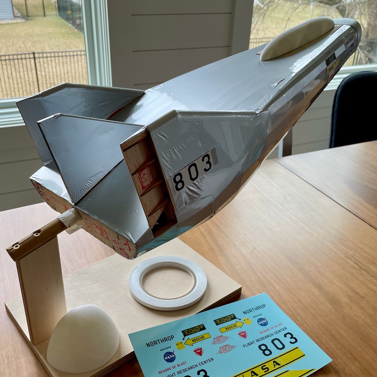
The above photo is as far as this iteration of the M2-F3 has come. You can see it almost completely covered—and my inability to get all the wrinkles out.
One of the last steps is to create the decals and markings from the original aircraft. Visible in the above photo are the temporary decals that are taped onto the covered model. I print them on a plain paper on a regular ink-jet printer, cut them out, and then tape them to the model to validate the scale of the artwork. When I am satisfied, I send the artwork to a shop online where they can be printed on a special printer and onto a special substrate to produce professional water-slide decals.
You can also see the water-slide decals in the above photo. (I have hesitated to apply them since the model still has a number of wrinkled surfaces.)
Iterate More
I have more work to do before I can finally put this model to rest.
I want to explore using vacuum forming in order to create a clear canopy and a clear nose piece for the model. The white stand-in pieces you see in the photos are simple 3-D printed shapes.
Additionally, I need closure on the control surfaces—need to make sure they can allow nylon hinges, have routing for linkages, function properly. Related, there should be a deck inside where I can mount servos, a receiver… As I say, I want this one to one day fly.
When I get drawn back to this project on a future date, I will push it further and hopefully get something I can call the first completed iteration. When I get to that point I will, as I do with many of my projects, make available a plan so others can laser-cut their own M2-F3.
I’ll update this page then.