Stereographer is a small application
I wrote to turn MPO files into a composite stereo image suitable
for printing and viewing in an old-time stereoscope. I talk about stereo photography, my incentive for
writing Stereographer and the process — including where AI helped and didn’t help me.
Experiments in Stereo
From time to time I enjoy dabbling in stereo photography. My interest in stereo images probably goes back to
the View-master™ and its reels (discs) with seven stereoscopic image pairs each (probably the case for a lot
of people). Peering into a View-master™ was like glimpsing a hidden, magical world. Even to this day it is
still exciting when I first view in 3D a stereo photo I took.
Something I have come to notice about stereo images — the good ones have me looking around within the
image the way that I have heard that a good painting does. For me at least that is something unique about
stereo photographs.
My earliest attempts at stereo photography date back to my film camera days. Having come across a few front-surface
mirrors (that I had either salvaged from somewhere or bought surplus) I built a cumbersome thing that you
could mount to the camera — it was something like a Kleenex box sized thing (made from foam-core, I believe)
that had the mirrors arranged somewhat like the prisms in a pair of binoculars. Imagine holding the camera
looking north — a pair of mirrors were joined at right angles in the center of the box (nearest the lens of
the camera) that split the view from the camera into a left half looking due west and a right half looking directly
east. A second pair of left and right outboard mirrors were angled so as to restore a north-looking view for
both halves through the camera viewfinder.
With the outboard mirrors angled carefully, the photographer sees the same image repeated in the left and right half
of the field of view (with a somewhat blurry vertical edge delineating the center). Of course the two halves though
are each from just a slightly different perspective — just like your eyes see the world.
The images I got back from this setup were not of the highest quality but it did kind of work.
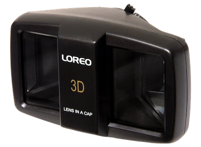
Years later I found out there was a cheap lens attachment that worked the same way that my clunky DIY setup
worked. Before the internet though, even finding out that some esoteric thing existed was a challenge.
A decade or so passes and consumer digital cameras replace film cameras. I would remember my early stereo photo
experiments and try to repeat them with the new hardware. My clunky mirror contraption was long gone but
with easy access to plenty of digital cameras (I was working in the ColorSync team at Apple at this time) I hoped
instead to mount a pair of cameras side by side to shoot stereo photos.
One hurdle is firing both cameras at the same time. Instead though I got lazy — I found I could create stereo
photos by taking two photos on the same camera — you just slide the camera horizontally a few inches between shots.
You have the obvious problem that if your subject moves between shots you blow the effect. But for just playing
around I accepted this limitation. I was surprised at how often it worked really well. Add a tripod, some sort
of sliding jig for the camera and you can get very good and repeatable stereo photos (try it with your phone).
I have had human subjects stand perfectly still between two photos and have been able to pull off a good stereo
shot. I took a nice stereo pair of Delicate Arch in Utah using the move-a-bit-horizontally-between-shots method.
While a few tourists were in both photos and moved between the shots, I was able to fix it in post. I ‘cloned’
the tourists from one image to the other in a paint program as though they had been static.
Compositing
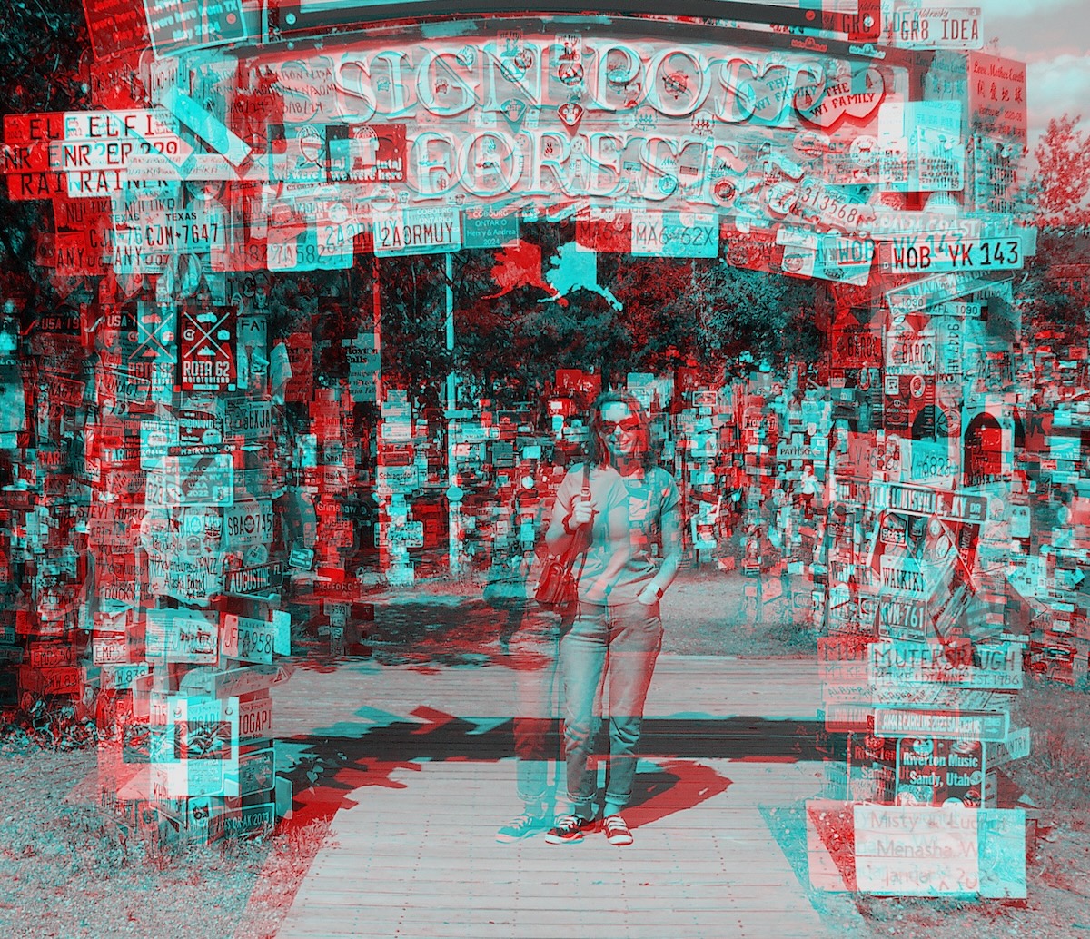
There are a number of things you can do with your left and right image pair. A fun thing to create is a red/cyan
anaglyph. You know, where you view the image by wearing a pair of red/cyan glasses? You can pull the image pair into
a paint document for this — giving them each their own layer. Anaglyphs works best if the source images are grayscale
so I would convert them to B&W first. After that use a tool like Levels to make the left image cyan (slam the Green and
Blue channels in Levels) and the right image red (slam only the Red channel). Set the top layer to Multiply compositing
mode, some aligning, cropping ... you’re done.
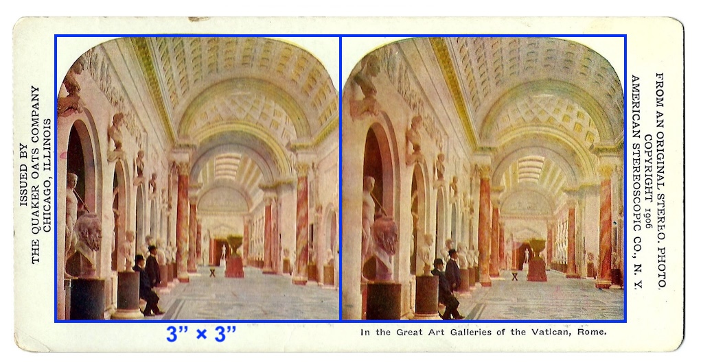
Instead though, I like the fidelity and clarity you can only get from the classic stereoscopic images — the kind that
you would view on an old-fashioned stereoscope. Finding a stereoscopic viewer is not impossible but is something of
an obstacle. Fortunately though, creating the cards from your stereo pair is perhaps even easier than the anaglyph.
(I like the fidelity and clarity of the old View-master™ reels as well but creating them is a challenge I have not
yet embarked upon.)
Surprising to me, the original stereoscopic cards were printed to a kind of standard: exactly 7" across and 3½" tall.
The left and right images themselves are exactly 3" square (well, there is the small arch above each image cropping them
somewhat) and they abut each other in the center of the card. There’s a ½" margin on the left and right, a ⅜" margin
along the bottom. You can create a kind of template document in a paint program to match this.
Choose at least 300 DPI and fill the document with whatever texture or color you prefer for the card itself. Scale your
images down to 3 by 3 inches and place them to the left and right of center.
As you see in the older cards, a decorative arch across the top of each image was popular. Adding a description lets the
viewer know something about the photo. Print the final image with a photo-quality inkjet and add a card stock backing to
give it some stiffness. Cut to size, round the corners if you can.
If this sounds a little more complicated than I previously let on, well that is why I wrote the Stereographer
application: to make the steps just up to printing and mounting much easier. I’ll talk about this in a bit.
MPO files
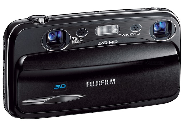
Back in 2010, FUJIFILM released the
Finepix REAL3D W3
stereo digital camera. It wasn’t terribly expensive but gave you two CCDs (and two lenses, etc.) and a cute
lenticular screen on the back that showed you an actual 3D preview of the photo you just took (or were
about to take). When I finally learned of it I bought one.
The FUJIFILM Finepix REAL3D W3 stereo digital camera.
The camera works best as a point-and-shoot and in this capacity it is not a bad camera. It has a manual mode
but it is so difficult to use that it is more or less worthless in that regard (no physical controls to change
shutter speed, f-stop).
There are not a lot of stereo digital options out there.
Lumix made a similar camera
but it is harder to find. There are people that have paired digital cameras and have figured out ways to sync
the triggers. A Raspberry Pi based stereo camera is being experimented with.
And there are always the lens attachments for standard cameras that give you a split pair of images.
The images the FUJIFILM W3 (and LUMIX DMC-3D1) create are MPO (Multiple Picture Object) files. It’s kind of an
unusual image file format that I understand is little more than a wrapper for multiple JPEGs. (So you’re definitely
not going to be shooting RAW with this thing.)
Sadly Apple’s ecosystem does not work well with MPO files. When opened with the Preview application I might see a
pair of images but they appear identical to each other — not the left + right pair that I am expecting. Importing
the images into the Photos app and you get just a single image. At the API level, creating an NSImage from an MPO
file, like Photos, also only returns a single image representation.
I found that exiftool can extract the left and the right image as JPEGs. Users
on the internet have shared command-line incantations for this, or batch scripts to automate the same. Early on I
relied on this workflow — extraction and then making stereoscopic image cards by hand as I described earlier.
And at an API level, developers on StackOverflow have suggested hacks that involve finding the JPEG markers in the
MPO data and passing appropriately bounded chunks of data to NSImage to recover each image within the MPO file. That
does work and I use it in Stereographer.
I found an app for MacOS called XstereO Player
that simplified my workflow considerably. It could open the MPO files directly and had various modes of displaying
the image pairs — including a ‘Stereo Card’ mode. Ultimately I would find it had one or two shortcomings though
— and as the developer does not appear to be maintaining it I decided recently to write my own app and implement
a few of the features that I wanted.
XstereO Player, despite lacking a few of my esoteric feature requests, is nonetheless a pretty solid app that
has support for various flavors of anaglyphs, etc. For my own, much simpler app, Stereographer, I
focused only on stereoscopic cards. XstereO Player is still available on the App Store and I can attest that
it still works on MacOS Sonoma.
And A.I. Helped
A few years before retirement I spent a year os so converting a van to an RV that the wife and I could travel
the U.S. in. The summer of 2024 turned out to be the year I made the long drive from Omaha, Nebraska to Homer,
Alaska to visit my dad. It turned out to be a 28 day drive and about a 10,000 miles round trip when all was
said and done.
For some reason (and back on the subject at hand) I decided to bring the stereo camera along and use it
exclusively to photograph the road trip. When I returned home I found that I had shot over 400 stereo photos.
That became then the incentive I needed to create the app, Stereographer, and implement those features
that I had found lacking in other software I had tried.
I have been AI curious and had experimented months back with Claude.ai. In that exrercise, ‘he’ had helped me
spin up a small map-based web page where I had had
no experience doing this beforehand. It had gone surprisingly well and so I followed up by trying out AI for
help with a few other Javascript-heavy, web experiments that I had been wanting to try. Those experiments
with AI-assisted development were a little more frustrating. I decided again though to lean on AI for this
new project as I wanted to do it using SwiftUI and I had not yet dabbled in that. (SwiftUI was beginning to
ramp up just as I was retiring from Apple — for better or worse I managed to put off jumping into it then.)
In general, I find AI to have been helpful for me when I am heading into an area where I have no (or little) prior
experience.
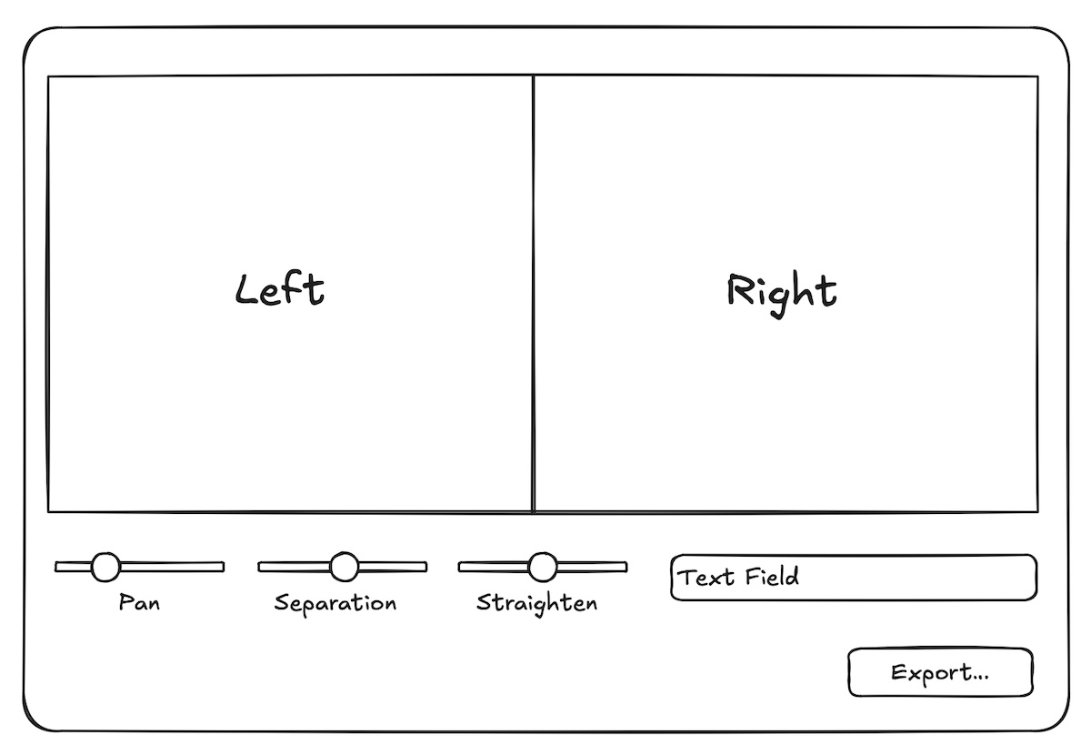
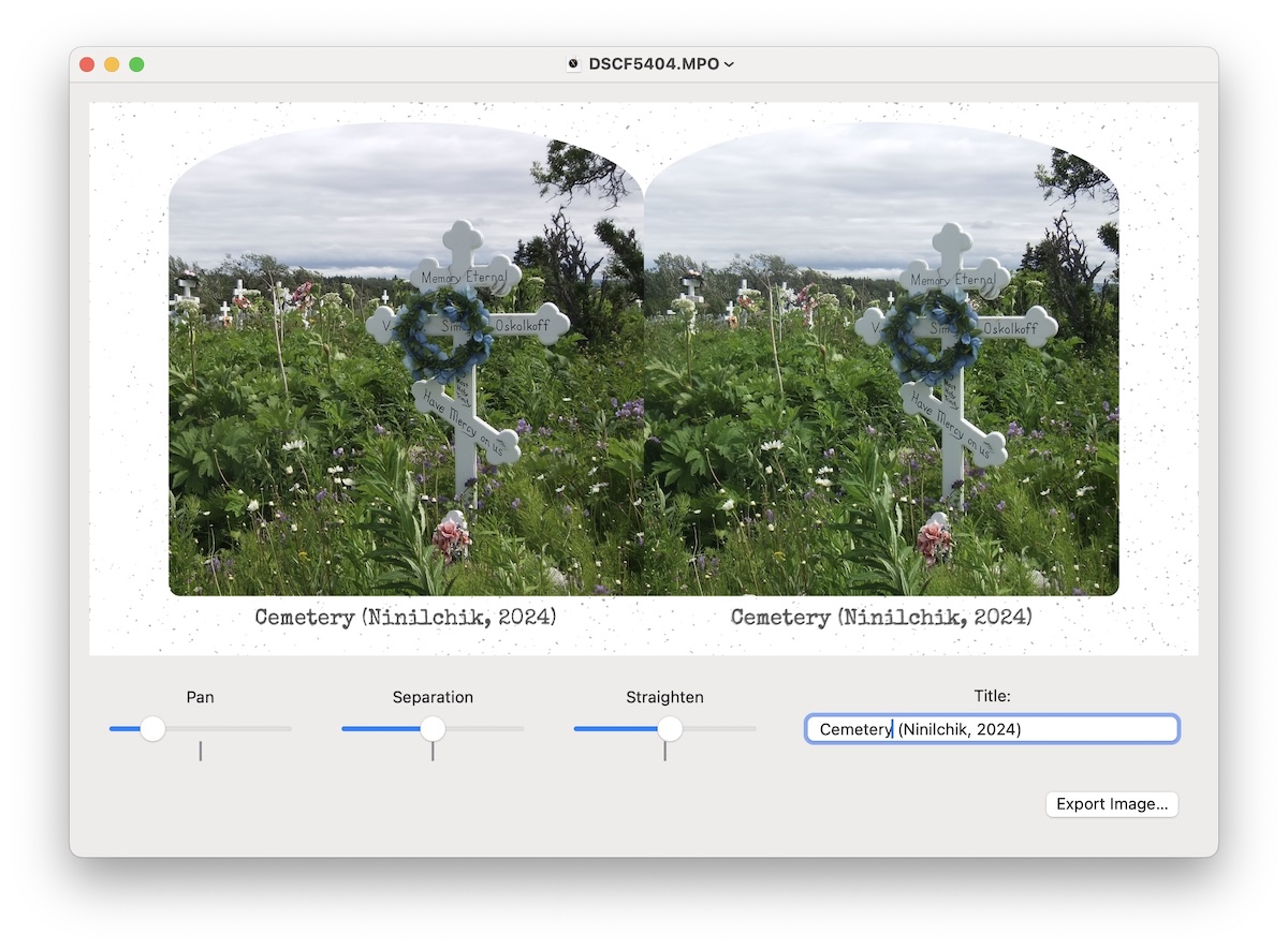
In my mind this 3D, SwiftUI app would be a simple document-based one where each document would get a window showing the
composite left + right image. An image resource would provide a mask — framing the two images (and giving them the little
traditional arch across the top).
Controls I imagined would include a Pan, Separation and Straighten sliders and a text field to add a description.
Finally a button would export the composite image so that it could be printed out.
How I imagined a document window would look.
With the above description I was able to come up with a reasonable prompt to start the development with AI. It began
something like, “I want to create a document-based, SwiftUI app for MacOS where each document window consists of an
image view above and a row of sliders beneath.”
As pieces of the app began to come together and compile, I could focus on more specific aspects of the code with prompts
like, “I want the Content to consist of a vertical stack containing the image view, sliders plus text field, and then a button.”
Later, “How do I get a tick mark on the slider?” Later still, “I want the text field to have a minimum width of
200 points.”
In this way it slowly came together. ChatGPT wasn’t perfect. And from time to time we would enter into a kind of circular
firing squad where I seemed unable to get AI to give me something other than what he/she/it had incorrectly given me
over and over before. More on that later.
Eventually we landed on this.
Pan and Separation
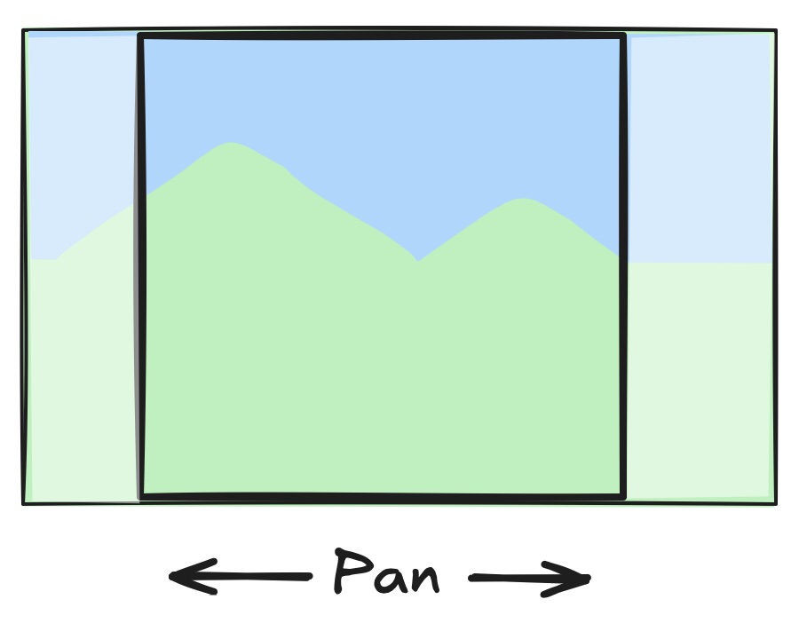
With the photos coming off the stereo camera having an aspect ratio of 3:2 means that some amount of cropping
is necessary to make each image square for the stereoscopic image. The Pan control gives the user control over
where to do the cropping. As you slide the Pan control left and right a square portion (the same square
portion) from the left and right images are composited to the final stereoscopic image in the content view.
How far the user can pan is simple math — essentially the height of the image subtracted from the width. Taking
this difference gives us a scalar. The range of the slider is -1 to +1 (with the slider representing zero when
in the middle of its range). So multiplying the value of the slider by one-half of our scalar tells us how much
to pan (translate) the source left and right images.
Something missing from the XstereO app was a means to pan the left and right images slightly toward or away from one
another. I call this ‘separation’ in the UI. It is essentially a bias added to the pan control. Moving the
separation slider one way might add a small amount of extra pan to the left image but will subtract the same amount of
pan from the right image. It therefore either pulls the images together slightly, or pushes them apart a bit.
I have found that for some images coming off the camera this can be an important parameter to adjust in order to make
the resulting stereo image ‘look right’. The bounds of each image act as something like a window frame within which we
view the little stereo scene displayed on the card. We expect that the things within the stereo view which are clipped
by the frame of the card should appear behind the card — depthwise. Sometimes though the images coming off the camera
don’t quite resolve that way — they create a kind of spatial dissonance that our brain struggles with. A flower, for
example, comes into the frame from below but the separation between the left and right versions of the flower are such
that it would appear nearer to us than the distance the stereographic card represents. Sometimes just pulling the images
farther apart resolves this spatial confusion.
The Separation control when not in the center (zero position) adds a bias to the left and right pan settings.
Since we had previously carefully scaled the pan to map precisely to the ‘pannable bounds’ of the source image, adding
a bias will in extreme cases cause us to pan past one end or the other of the original image. To avoid this happening
there is clipping of the final left and right pan values once the separation bias is applied.
Straighten
The photos you take with a stereo camera are necessarily in landscape mode. (If you were to hold a stereo camera at
any other orientation you defeat the proper stereo effect.) Nonetheless I found a handful of the photos that I took
on my road trip where I had not held the camera exactly horizontal. When I considered it though I understood that
the math involved to add straighten functionality would be challenging.
Without the Straighten control the transform I had to map from the left and right images to the resulting
square destination was a simple scale and translate (and clipping of course). The translate (panning) I
already more or less described. The scaling required was simply to go from the source image size (the
height actually) to the destination size (height). (Since I had decided to target 450 DPI for the resulting
stereoscopic image and the resulting image pairs are 3 inches square, the scale factor was whatever was needed to
bring the image into 1350 by 1350 pixels.)
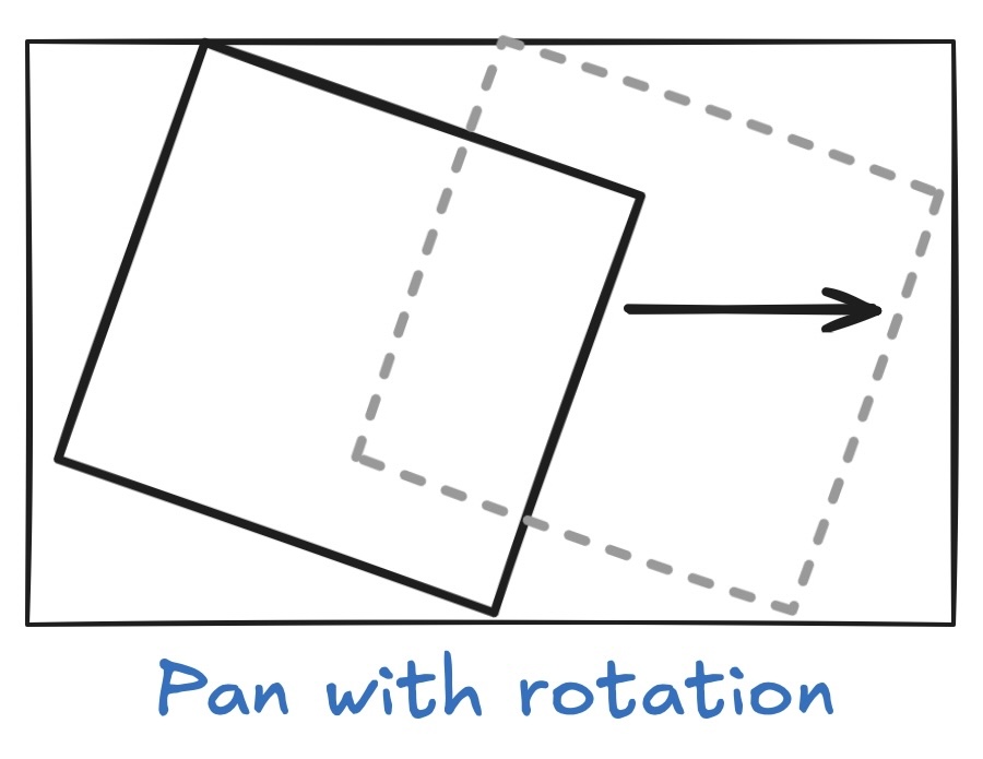
Adding a rotation to the transform opened up a whole new can of worms. For starters, if you’ve ever played
with transform matrices you know that the order of operations is important. Do I scale then translate and
then rotate? Or scale last? Who knows? I have spent hours in the past on similar tasks trying seemingly endless
combinations to wacky results.
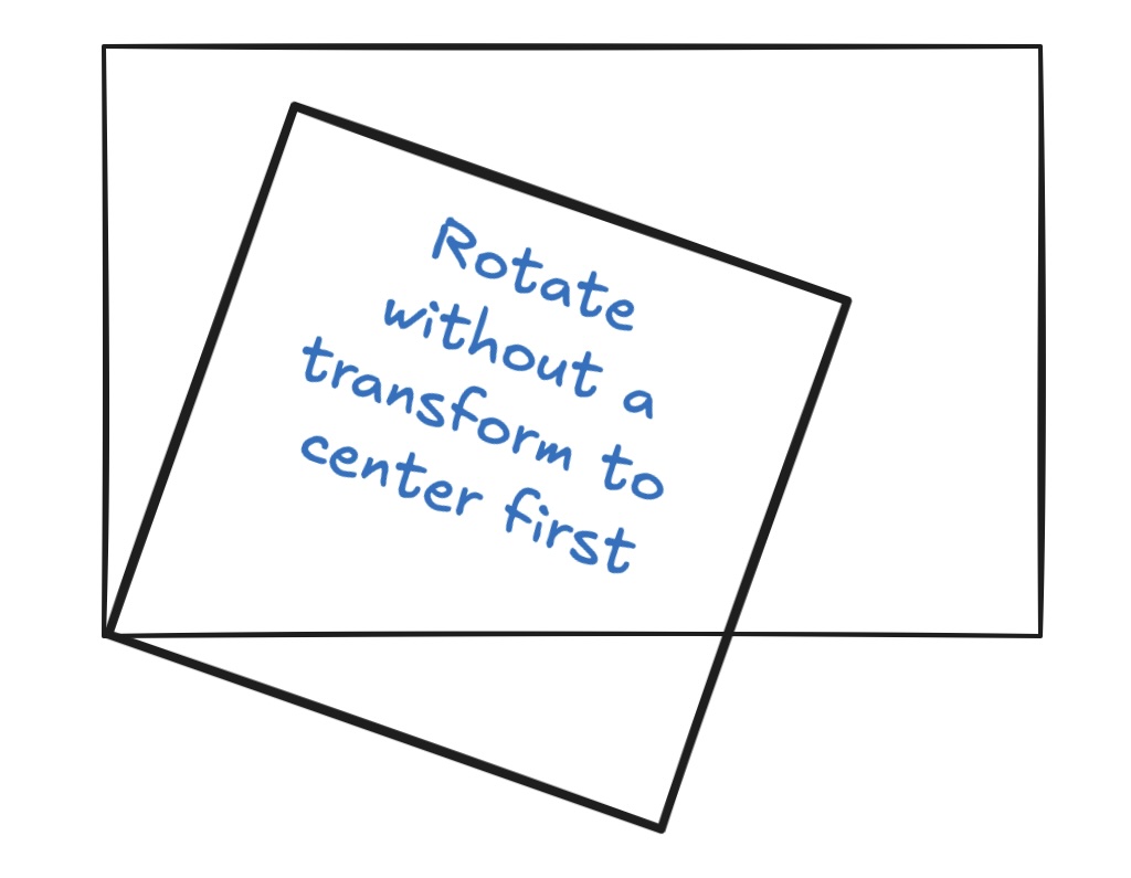
And you may also know that rotating the image about the center requires an extra set of translations to center the
transform before you apply the rotate (and then you need to de-translate after).
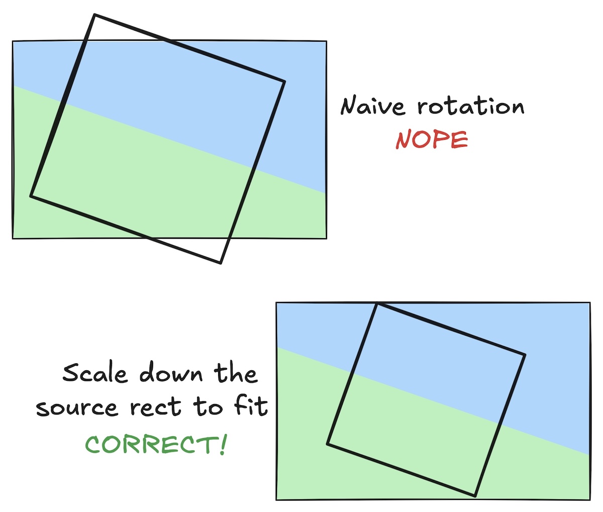
An added complexity comes when you consider that a naive rotation would bring in content outside the bounds
of the source images. What you really want to do when the user rotates the image is shrink the bounding
square by an appropriate amount to keep it within the source image bounds.
By the way, when you look at the above diagrams, realize that the CORRECT way will result in the image appearing to be
scaled larger. While the source rectangle is drawn above smaller than the naive rotation, remember that this is
illustrating the source image — the destination is still the same size and so the smaller square gets scaled
more in order to fill it.
Something that surprised me — when you apply a rotation as described, you actually need make no additional adjustments
to reign in panning. If you visualize the upright square that the new rotated one would be inscribed within, it is the
exact same square we have if there were no rotation. In other words, the simple math we did earlier to limit pan to keep
it within the source image rectangle remains unchanged.
A.I. Falls Down
So I mention the above issue — rotating, scaling to allow for the inscribed square — because it was one of those places
where ChatGPT went ’round and ’round with me.
To simplify the problem a bit for ChatGPT, I made the source image a square aspect ratio. My prompt then went like this:
“I’m trying to render from a square source image into a square destination CGContext. If I allow a rotation to straighten
the source image, how do I apply the correct transforms to the CGContext to get the largest square source image scaled
and centered in the destination CGContext?”
The answer (code) I got back incorrectly computed the scale. In fact it did the complete opposite of what I wanted — it
computed a scale that would contain the entire source image in the destination. In common parlance it was trying to do
a ‘fit’ from the source image to the destination, but I was asking for it to give me a ‘fill’. Re-reading my prompt though,
it’s possible I was not clear?
I tried to make it more clear though in a followup prompt: “While the transform you created keeps the entire rotated source image
within the destination CGContext, I want the source image to completely fill the destination CGContext.”
And yet I got back a reply (code) that was more of the same.
Me: “I am not seeing the destination context being filled. If there is a rotation I expect the source image will naturally
be clipped somewhat so as to fill the destination.”
And again ChatGPT comes back with similar and incorrect code.
After we ran around a bit more I finally gave up. I had earlier asked it to compute the scale of the largest inscribed rotated
square within a unit square and it gave me the correct math (one over the absolute value of sine of the angle plus the absolute
value of the cosine of the angle). So I was able to substitute the trig for the bozo scaling factor ChatGPT had been giving me.
Making Cards
The application eventually came together of course and I began processing the 400+ photos I had taken.
(On my machine at least) the composite image that is displayed in each MPO document’s window is ‘actual size’.
That is it is 7" × 3½". The image pairs too should each be precisely 3" square. I can’t stare at two images 3"
apart and resolve them into a single stereo image — that is where the stereoscope is needed. (There is a
cross-eyed viewing technique if you swap the left/right images, but that would be a strain — and if someone
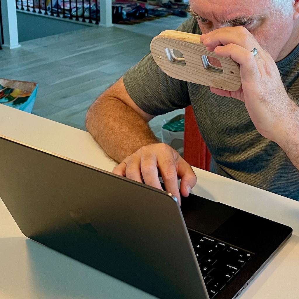
hits you on the back your eyes can get stuck that way. That’s a joke.) I do have just the lens portion of a
stereoscope that I can hold some distance from my laptop display and get the stereo effect without having to
first print the image.
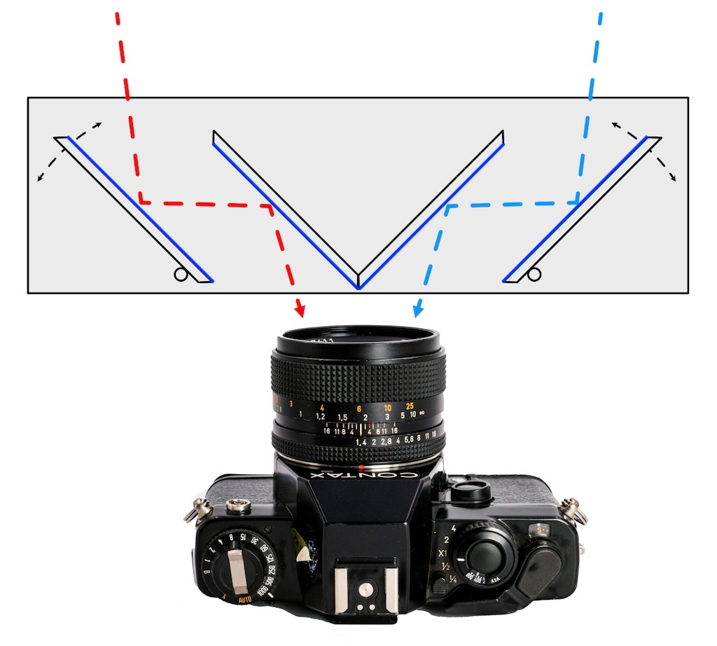
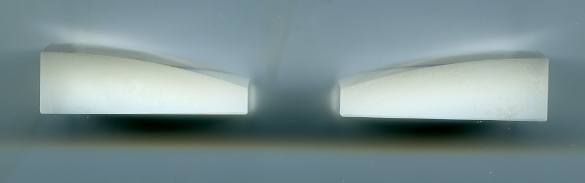
Stereoscope lens are a little unusual. Imagine a standard convex lens, such as the kind you find as part
of a magnifying glass, but cut it vertically into two halves. Now swap the two halves — giving you something
like a butterfly arrangement. This is how optically the stereoscope allows our eyes to relax but still see a pair
of images that are farther apart than our pupils.
By viewing the image in stereo ‘live’ I can adjust the pan, separation and see the results in real time. In fact though you
can probably adjust these settings without real-time stereo. In adjusting the pan setting sometimes there is a foreground
object that is best clipped if you can view the image in stereo, but generally you can adjust the slider in 2D alone.
Using half a stereoscope to view an image on the MacBook.
When I am happy with the settings on an image, I type a title/description and then Export Image. Stereographer produces a
450 DPI JPEG with minimal compression. I have a Pixelmator Pro document that I created at 450 DPI that matches in size the
glossy photo paper I use in my EPSON Artisan 1430 inkjet printer. I can fit three of the stereoscopic images in a document.
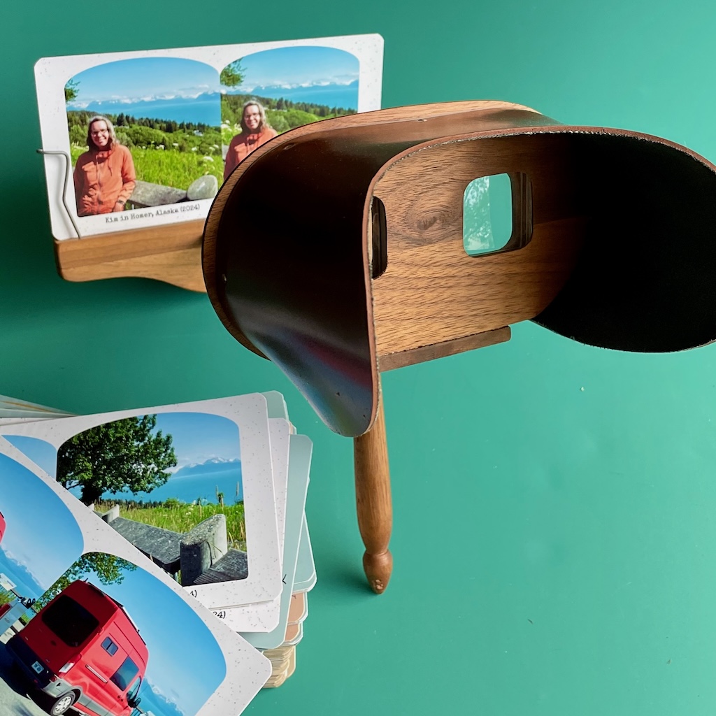
These 3-up documents I then print on the aforementioned EPSON. To give them a stable backing, I glue a sheet of 110#
card stock to the back of each printed sheet. The next step is to cut the cards to 7" × 3½" and the final step
is to cut the corners off each card.
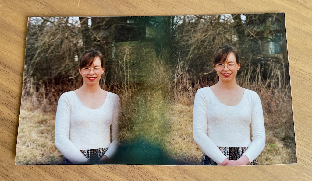
A ‘Holmes style’ stereoscope and modern stereoscopic images I created.
Furthermore
Sources to Stereographer are on GitHub. If
you have a Mac you can try it out — I have checked in a couple of MPO files in case you have none.
If I were to extend Stereographer I would like to have a ‘New Document’ option that brought up a window much
like the current document window but where the left and right stereo images normally appear there would instead be
text that reads “Drop Image Here”.
The above feature alone though assumes that the two images are the same size, aligned correctly, etc. I am not sure
how useful it would be without a lot of additional controls.
I could add a separate scaling slider to give you the ability to zoom in on the image. With stereo images though
zooming in also scales the separation between the images — not always desirable.
Others, not me, might like a “Swap Left and Right Image” checkbox to allow you to create a cross-eyed stereogram.
An anaglyph mode would be kind of fun to have from time to time.
Anyway, if people are interested I could talk about how to build a simple stereoscope, or my failure to create a
lenticular stereo image, or if anyone is interested in hearing more about my experiences and experiments in stereo
photography, just holler.