Something that struck me reading about the history of the Apple I computer was the fairly simple “ASCII bus” that it used for input and output. As I understand it a hobbyist back in the day could get an ASCII keyboard that quite literally presented as an interface a header giving 7-bits of ASCII and an additional strobe pin that indicated that a key had been pressed. Press the “A” key on the keyboard and the 7-bits representing the letter “A” in ASCII would be set high/low on 7 output pins and the strobe pin would momentarily go high. Needless to say, the Apple I was wired up in such a way that when the strobe pin pulsed it would immediately fetch the 7-bits of ASCII from the keyboard.
And just as simply, to display a character the Apple I would output ASCII in the same manner. In the output case, another device similar to the TV Typewriter would look for a similar “strobe” and push the character into a buffer that was constantly being read from and displayed to a television display.
In short, ASCII comes in from a keyboard, ASCII goes out to the TV buffer.
The Adam74 is a little project that tries to act as the latter half of the above “ASCII bus”. It is in short a little terminal that a hobbyist might enjoy using for a small 8-bit computer they’re experimenting with.
As described above, it relies on 7 pins to represent a 7-bit ASCII character and another pin that the connected device strobes in order to tell the Adam74 that there is a character waiting on the input pins to buffer and display. The prevalence of easy-to-interface small LCD displays and inexpensive microcontrollers to drive them made this project a no-brainer.
Like a terminal, the Adam74 handles wrapping of text, scrolling. It also handles many control codes like carriage return and bell. Other control codes are re-interpreted to give a simple cursor control interface, etc.
Early Prototyping
I think it was those little LCD displays that first sparked the idea of a mini terminal. But, wow, they’re small.
The typical 3” LCD display is, at best, about 320 x 240 pixels. My ideal terminal would be able to display 40 columns and 24 rows of characters — but this would require a font that would be legible at only 7 pixels wide and 9 pixels tall (per character). When I started experimenting with these tiny displays I found that I could just barely squeeze a mono-space font in and still get a legible 40 x 24 character display. (Yeah, ha ha, forget your 80 column upgrade.)
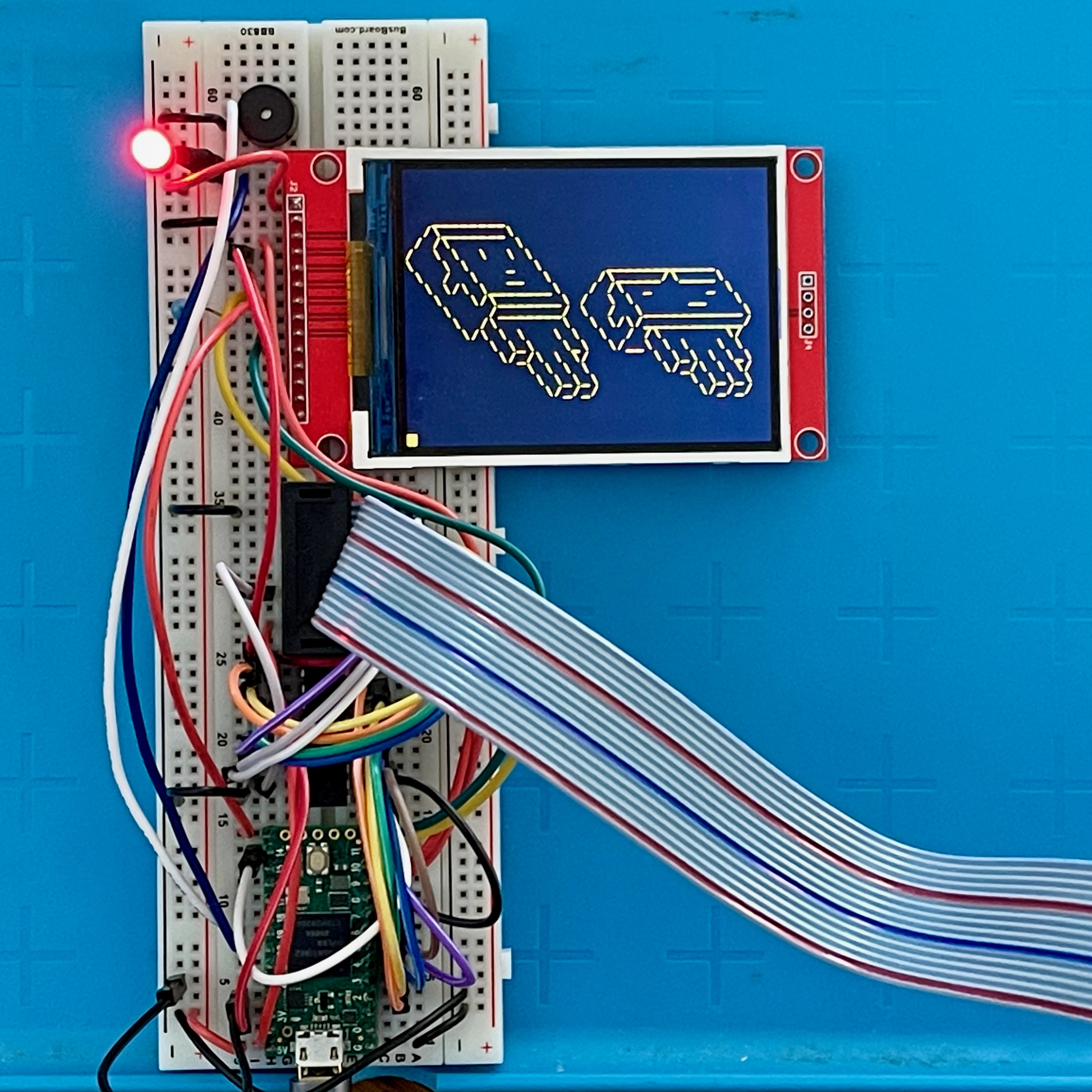
I love working with the Teensy so I started my breadboarding with a Teensy 2.0. It worked beautifully, if only a bit slow when scrolling.
I tried to figure out hardware scrolling on the LCD device but was not successful (I seem to recall that the hardware scrolling was limited to scrolling along the long axis of the display). To get better scrolling performance I moved up to the Teensy 4.0. That did indeed paint the LCD much faster and so brought the scrolling speed up to something more reasonable.
To make the connection to the Adam74 more manageable I decided to go with a ribbon cable. Even with power and ground (and a pin that might indicate that the Adam74 was busy) you could still carry all the signals with less than a dozen wires. And so when I created the first PCB for the Adam74 I incorporated a 14-pin IDC connector — more than enough wires to carry all the data.
And so to test the Adam74 and its new ribbon cable connection I breadboarded up another Teensy that would server to push ASCII to the terminal. And, sadly, I started to see some anomalies.
When I dialed up the test program to start sending ASCII full tilt (just sending the characters for “Hello World” as quickly as I could) I started noticing some glitches. They scrolled too quick for me to be sure so I pointed my phone at the display and filmed for a few seconds. When I played back the video I had captured, sure enough, some of the characters were just wromg.
I played a bit with some of the parts of the software that controlled timing — adding a delay here and there, but I wasn’t seeing anything like a silver bullet that fixed the problem. I began to suspect the problem was the ribbon cable.
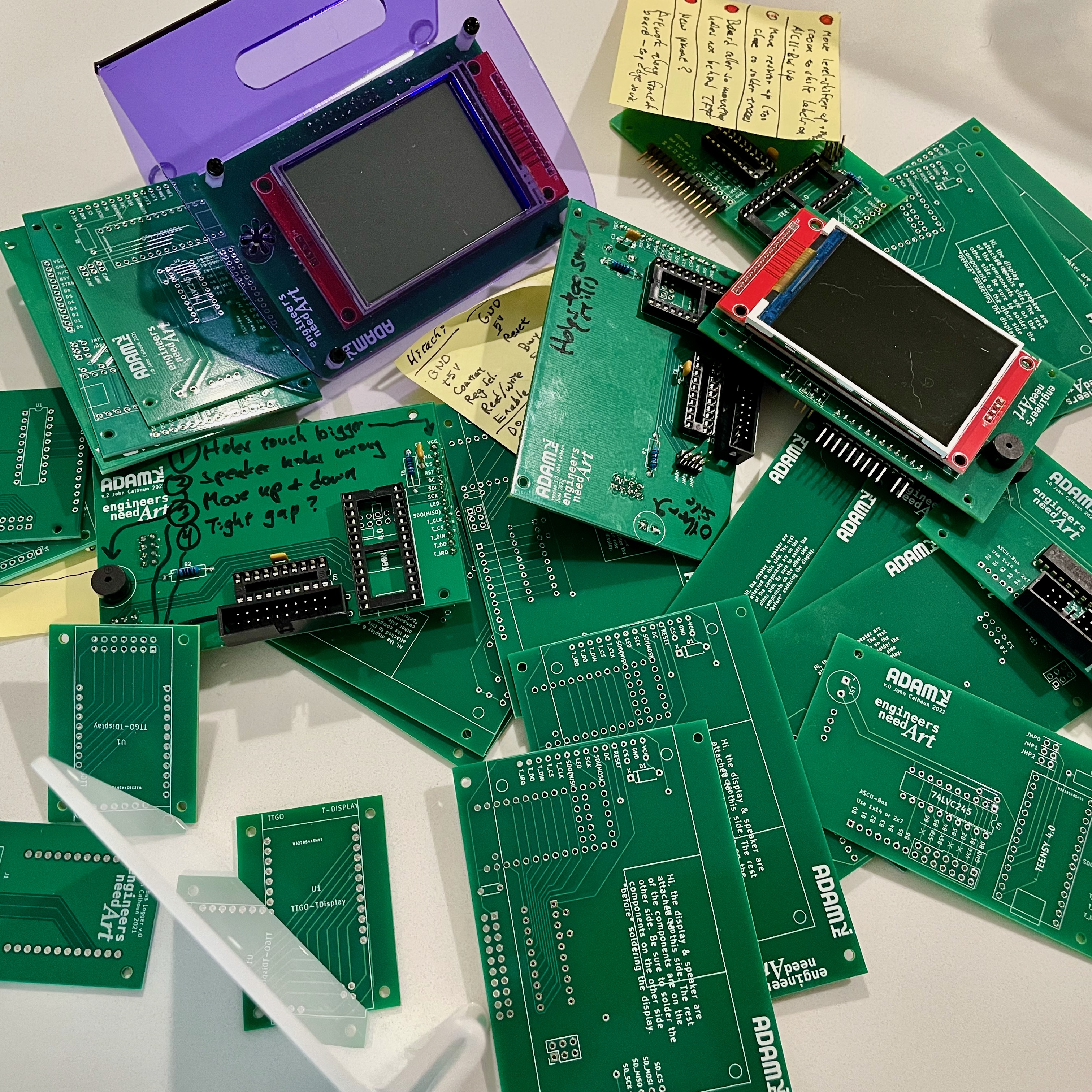
So as a test I pulled out the ribbon cable connecting the Teensy to the Adam74 and ran my usual spaghetti of breadboard wires. This time I saw no glitches in “Hello World”. Perhaps the ribbon cable was carrying too many sensitive signal lines in too close a proximity to one another. When I looked online I saw that it was not unusual to dedicate every other wire to ground in order to isolate the signal wires from one another and avoid this kind of crosstalk.
Begrudgingly, I prototyped the next PCB to use a 20-pin DC connector (and 20-wire wide ribbon cable) with every other wire carrying a ground signal. This time, no glitches when using the ribbon cable.
It was time to finalize the design, come up with a name, come up with a stand.
Inspiration
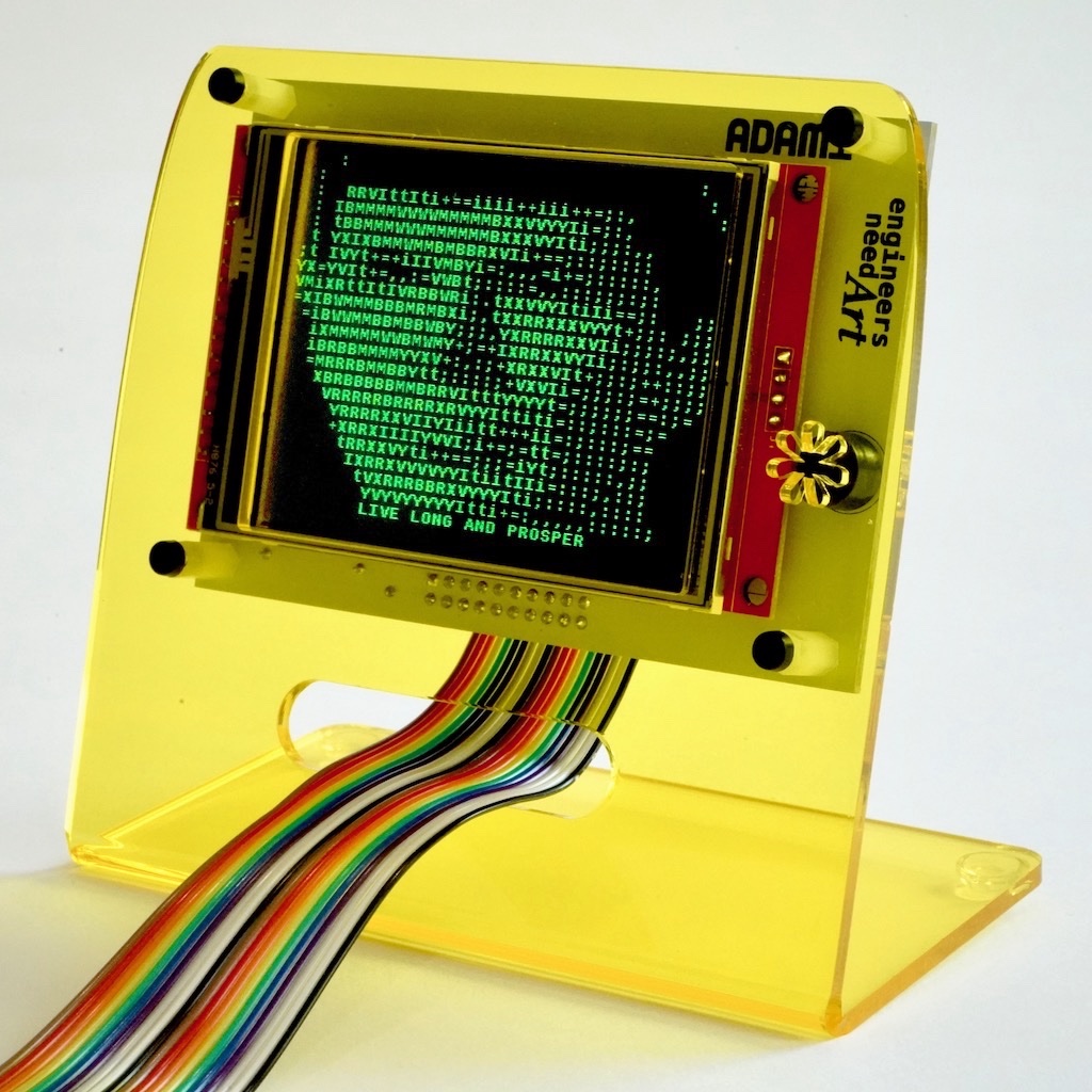
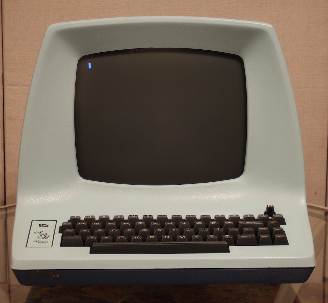
In doing research on the early terminals it was no surprise that I would stumble upon the ADM-3A terminal. And it will not surprise you that I drew inspiration from this machine for both the general shape of the acrylic stand I designed for it as well as the name itself.
The “74” in Adam74 is meant to suggest the era: sometime around 1974.
Other Features
There is a tiny speaker on the Adam74. This is there because it is one of the more truly satisfying things in my mind to send the control code for “BELL” and get a little “beep” from the terminal. I remember enjoying this even back in high school when I sat down in front of my first Apple II and typed <control> G.
Initially my Adam74 had a small LED to indicate the power was on but I ultimately removed it because I feel there are just too many LEDs on devices that indicate the power is on. Besides, you hear the beep sound when the Adam74 boots up and you should have a blinking cursor prompt after.
So that you could interface the Adam74 across a wider voltage range, I added a level-shifter chip.
Also, once I accidentally swapped the power and ground wires and let out the magic smoke from the LCD panel. After that mishap I added a small diode to hopefully protect the display should it happen again.
Uses
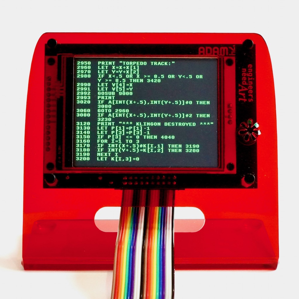
In my mind, the kind of hobbyist building a vintage 8-bit computer of the Ben Eater school might find the Adam74 a fun output device. Perhaps they can implement a BASIC interpreter on their small breadboard computer and use the Adam74 as their display. Or maybe someone will implement a Snake game or Star Trek from 1971.
The hard-core Ben Eater acolyte may dislike the Adam74 as it uses a modern display, microcontroller driver. I know the old Hitachi-based LCD display is a popular device to interface with — the Adam74 is perhaps just a little bit of a stretch from one of those. There are hobbyists out there building their own breadboard graphic cards to drive VGA monitors — the Adam74 is perhaps somewhere in between that and the Hitachi.
Availability
The source code as well as Gerber files (and an SVG file you can use to cut the acrylic stand) are up on my EngineersNeedArt GitHub repo.