ASCIIboard
Controllers
Early Layouts
Layout
Hand-wired Prototype
PCB
Daughterboard
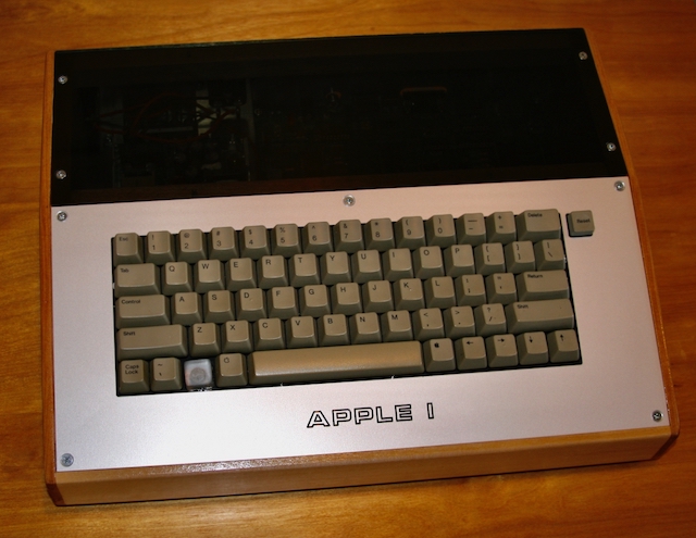
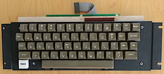
Some years back I bought an Apple I replica kit from Briel Computers. I was a little disappointed to have to use a PS/2 keyboard with the machine — especially as I intended to build an enclosure for mine … looking in spirit like a 70’s computer.
From a facsimile of the original Apple I documentation I understood that Wozniak had expected a hobbyist to be able to construct or purchase an “ASCII keyboard” — that is, a keyboard with an interface that would present the 7-bits of ASCII for each user keystroke. While perhaps available to the hobbyist in the 1970’s, they are near impossible to find today (I have seen vintage Clare-Pendar ASCII keyboards, for example, asking $2K to $5K on eBay).
At the time I built the Apple I replica you could still find Apple II keyboards on eBay going for maybe $50 or so. I ended up buying one of those and programming an ATMEL microcontroller to scan the Apple II keyboard and present ASCII to the Apple I replica.
Below is my Apple I replica, custom enclosure, and Apple II keyboard.
In fact the code I wrote for the controller was poor and I never did solve debouncing the switches to my satisfaction.
So that was 2007. The mechanical keyboard bug has been resurfacing but these days vintage Apple II keyboards are even more scarce. Nonetheless, today it is much easier to design and lay out your own PCB, populate it with high quality mechanical switches, marry it with an inexpensive, easy to program controller (and so much open-source out there as well) and top it off with any of a variety of custom keycaps.
I set out to design an ASCII keyboard, my ASCIIboard, for the 21st Century.
So many controllers…
A controller is the brains of a keyboard. It is a sliver of silicon that is programmed to scan the switch (key) matrix looking for a keypress and, in our case, present the ASCII equivalent of that key on a row of 7 pins. (I should add that an 8th pin, called the strobe pin, also will be “pulsed” to indicate that a new keypress, new ASCII, is available on the other 7 pins.)
It is either a blessing or a curse that today there are so many microcontrollers, tiny single-board computers, to choose among to act as the keyboard controller. Nonetheless, when looking at open-source software available and just generally what people are using for their own custom mechanical keybopard builds the list narrows to a handful.
As the Raspberry Pi is becoming more of the go-to in the world of small, inexpensive computer boards (with lots of I/O pins) it is not surprising that many people are experimenting with this very capable board to drive their keyboard projects. For example, look around and you can find tutorials using Python to design such a thing.
But the real workhorse of keyboard controllers appears to be the Teensy. I don’t know a lot about the Teensy family of microcontrollers but you can certainly read up about them yourself. It’s clear from the Teensy website however that older versions of the Teensy are being deprecated while newer, more capable versions are rolled out.
For reasons that are no longer clear to me, I landed on the Teensy 3.2 for my forray into building a mechanical keyboard from scratch.
Around the outer perimeter of the board there are 24 digital I/O (often called GPIO pins to mean “General Purprose Input Output” pins). That’s a good deal of pins.
Sadly, to keep the footprint of the Teensy 3.2 small, another 10 GPIO pins of the Teensy were relegated to the underside of the board. As I am not clear as to how I would easily interface these with a PCB, I considered those pins unaccessible.
But part of selecting a microcontroller is deciding how many pins you need and the easy to access 24 GPIO pins of the Teensy 3.2 seemed adequate to me. A matrix of 8 by 8 switches (that would allow a keyboard with up to 64 keys) can be addressed with 16 of the GPIO pins (8 rows, 8 columns). That still leaves 8 GPIO pins for the output.
In looking at the Teensy web page today, with more experienced eyes, I can make a better case for selecting the Teensy LC rather than the 3.2 for my mechanical keyboard. It’s almost half the price of the 3.2 and appears to add fairly easy accessibility to a couple more GPIO pins.
Early Home Computer Keyboard Layouts
Which keys should I have on the ASCIIboard? Which to include, which to leave off? How should they be laid out?
I started by researching the old ASCII keyboards, the Apple II keyboards, etc.
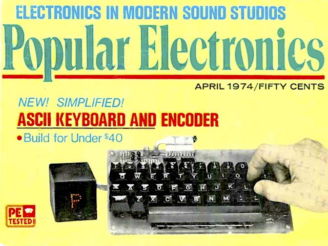
Popular Electroncis, April 1974 featured a DIY ASCII keyboard on their cover. (It’s clear a young Steve Wozniak saw and devoured this issue.)
As a keyboard it is pretty bare-bones with only 48 keys (two of which are left off the PCB but included in the matrix as user-definable). Compared to a modern keyboard you might notice the complete emptiness to the left and right of the space bar. The only modifiers are SHIFT and CTRL (to create those all-important control ASCII codes — the first 32 ASCII codes, in fact).
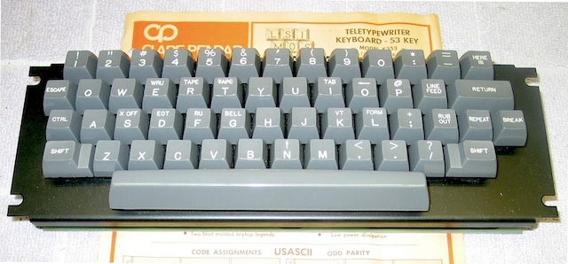
Up from 48 keys, the commercially available Clare-Pendar Model K353 sports 53 keys. They added the additional right-hand SHIFT key and dedicated control keys for ESCAPE, LINE FEED, RUB OUT (backspace?), as well as something called, apparently, HERE IS. REPEAT and BREAK round out the extra keys.
Curiously TAB is not yet it’s own key. And CAPS LOCK too is missing — but considering that 8-bit computers were often always in caps mode I guess it would be considered redundant until lower-case became more common. Also missing, the tilde (~) key.
The Apple II keyboard hewed close to the Clare-Pendar. It dropped LINE FEED, RUB OUT and BREAK but added left and right cursor keys. (HERE IS, whatever that was, is now RESET.)
I dont intend to present a dissertation on the evolution of computer keyboards so we’ll just leave it here. The above does capture the typical early 8-bit computer experience and as you can see a minimal layout reigned.
Creating ASCIIboard’s Layout
A fascinating protyping tool on the internet is keyboard-layout-editor.com. I won’t try to give you a tutorial on using it (and there are a lot of capabilities that I did not even begin to explore) but you should probably start by selecting some of the keyboard presets you’ll find in the Preset menu on the site.
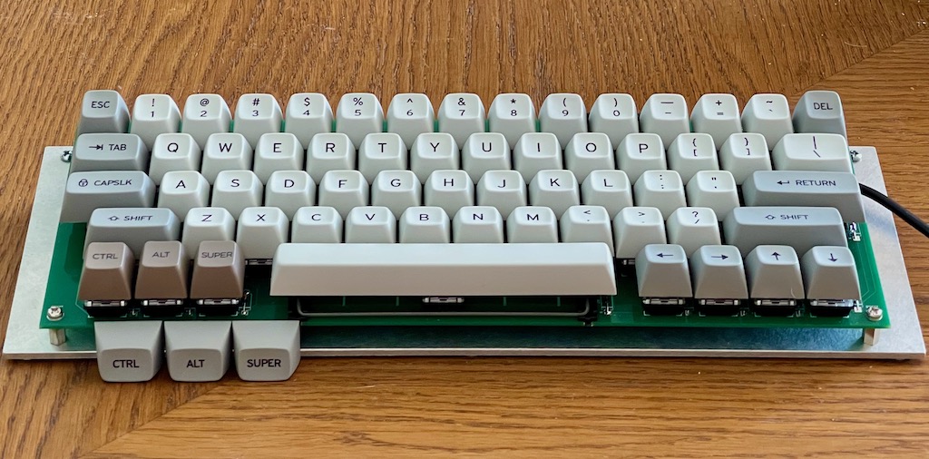
I experimented with it enough to come up with the layout you see in the following image.
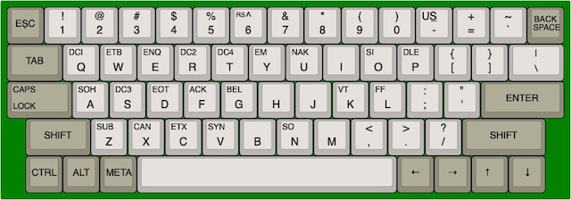
Not 52 keys or 53 — the above layout has 62 keys. Looking both to the left and right of the space bar makes it clear that I eschewed the minimalism of the 8-bit era with a nod toward keys expected on modern computer keyboards. Why?
As I investigated deeper into using the Teensy for controlling my keyboard (and this is likely true for any other board) I began to see that my ASCII keyboard could also function as a vanilla mechanical USB keyboard — making it something of an interesting hybrid.
The idea appealed to me that the keyboard could have this dual use. And if I were to make the keyboard available to others I imagined the ASCIIboard would have a broader appeal with this feature. (Purists could leave off the offending keys and key switches.)
I can of course refine the layout in the future as I spend more time using it. As with everything, as far as I’m concerned, it is always okay to continue to iterate.
Always Be Iterating
With a layout chosen the next step was to figure out how the 62 keys would be addressed — how they would be organized into a matrix — rows and columns of keys.
Something common among others who have wired up their own keyboards is to recognize that there is a natural 5 rows in a typical keyboard layout like the one I created. Columns are a little more complicated both because the columns on a keybpard layout are staggered and because the keys vary in size (board real estate). But looking casually at the ASCIIboard layout I might call out 15 columns (the top-most row for example consists of 15 keys).
You could sketch out a fairly clean 15 by 5 matrix to include all the keys in the above layout. (Doing the math of course, a 15 by 5 matrix could in fact address 75 unique keys but with large keys like the space bar there are clearly going to be “holes” in our key matrix.)
But then there’s the rub for me: 15 by 5 eats 20 of the GPIO pins of the controller. For a 62 key keyboard the optimal, minimal matrix would be an 8 by 8 one, requiring only 16 GPIO pins. It was clear to me I would lose sleep at night if I copped out and went with anything more than 8 by 8.
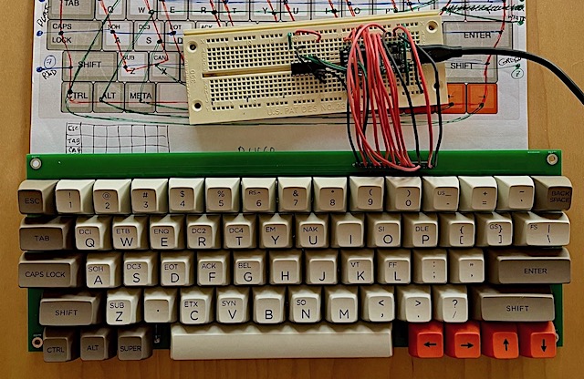
The price I pay for engineering purity is of course the labyrinthian path for the rows and columns I was forced to impose on the keybpard layout. See the following:
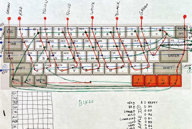
I don’t expect you to be able to make sense of the above sketch. But it is worth pointing out the orange-red marks that look like hooks sweeping in from above the keyboard — there are five fairly uniform ones across the middle of the keyboard. These are what my “columns” look like in order to touch on 7 or 8 keys each.
In case it isn’t clear, every key on the keyboard must be attached to exactly one column and exactly one row. The reason is of course electrical: we will scan each row and column in software looking for evidence of a closed circuit. If we detect a closed circuit, and therefore a key press, we will know definitively which key it is by the index of the row and column we are scanning at that instant. Esoteric: there is an issue of “key ghosting” that we need address with diodes but I’ll discuss that later.
A row or column may have as many keys as you like but as per the criteria I set for myself, each row and column should each have 8 key switches. Because I have 62 not 64 keys, there will be two intersections on the matrix where no key exists — therefore not all rows and columns will have 8 keys (but most will).
While a bit baroque, the above sketch shows the hookup diagram I had settled on and I could now proceed to building a physical protoype.
Hand-wired Prototype
I happened to have a “plate” (as they’re called) for a 60% keyboard layout (as it’s called) that I had picked up on aliexpress. I had also picked up about a cup’s worth of Gateron key switches that are of the variety that snap into these plates.
I just want to take a moment here to say how curiously deep a rabbit hole you can go down when you begin to venture into the world of mechanical keyboards and their fans. There are plates, PCBs, dozens of varieties of key switches, lubes, O-rings, custom cables, custom keycaps, custom cases, programmable LED backlights, minimal ortho-linear layouts, split keyboards, and on and on. Some fans take their obsession with mechanical keyboards to an artistic level of self-expression (and sink a staggering amount of money into them as well I might add). If you are not familiar with these modern keyboard artists, spend a little time in the r/mechanicalKeyboards subreddit.
I mentioned earlier that diodes were needed to prevent ghosting of keys. It’s a rather tedious thing to try to explain but suffice it to say that when more than one key are pressed at the same time (like the shift key and any other key for example) it is possible that, due to the geometry of the keyboard matrix and the well-known eagerness of electrons, that not two but three keys may be detected electrically when scanning the rows and columns via the controller chip. Two of the keys are of course really down but the third is a phantom key that behaves electrically as though it is a closed circuit as well. The diodes act as one-way streets that prevent these electrical U-turns that fool our controller. Search the web if you want a better explanation than that.
It happens with me and things electrical that often a concept is completely lost on me. The Sudoku that is key-matrix ghosting is sort of like that and I just accept that I need to add a diode for each key and I get on with my life.
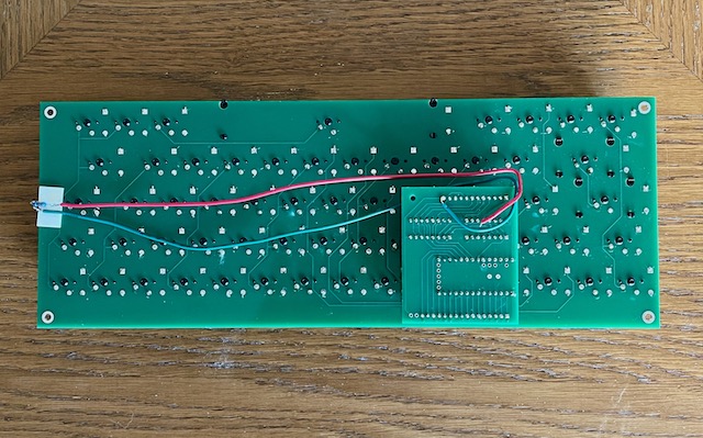
The diodes are tiny glass things (like Indian beads on a wire) and so not very clear in the following photo of the bottom of my hand-wired ASCIIboard prototype. I think you can appreciate though the insane crisscrossing of wires I had to solder.
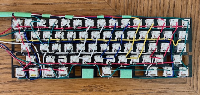
Oh yeah, that’s painter’s tape and there is also hot glue — underscoring the proto in prototype.
The smartest thing I discovered pushing this stone up hill was to use a spool of bare bus wire that I had lying around (since the old days of wire wrapping). Criss-crossing bare wire of course would have been a truly stupid idea but I found I could strip off insulation from some slightly larger gauge wire and then string short pieces of the tubing-like insulation over the bus wire as I went along. This insured that there would be no accidental short circuit where two wires crossed and was considerably faster than cutting and stripping each wire.
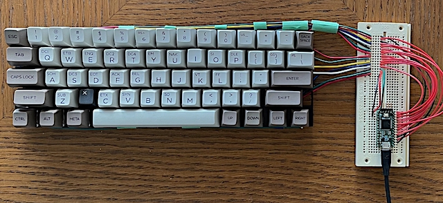
From the above photo you can see how all the row/column wires run out to a breadboard. The lower half of the breadboard then holds the Teensy — a bouquet of wires joining rows and columns to the GPIO pins. It’s not pretty but is enough to start writing software.
Lacking stabilizers for the wide keys like the spacebar, the result is a rather sloppy keyboard. But after knocking together a quick hello world program in software, it was shown to also be a functional keyboard. Hello indeed.
PCB
In hindsight I wonder why I even bothered to so tediously hand-wire a prototype. Maybe it was because, as I mentioned, I happened to already have the plate and keys on hand. Maybe too I wanted to see the software working before pulling the trigger on the rather more expensive outlay that a large PCB would be. If you didn’t know, PCBs are more or less priced by the square inch and often have minumum board orders. I suspected but didn’t yet know at the time that a large PCB suitable for even my somewhat modest keyboard would approach $100 (U.S.).
Happy though that the software was going to work, I raced to knock out a PCB to make the hand-wired monstrosity obsolete as quickly as I could.
Here’s how I approach learning to use really user-unfriendly software — like, take for example, KiCad: the way I approach learning KiCad is to have a project I really, really want to realize — and KiCad is really the best software out there to make this happen. (Or it’s the free solution, or the popular solution or whatever.)
The ASCIIboard then became that goal then and I rolled up my sleeves and got to learning.
Again, I can’t hope to include a KiCad tutorial here — nor am I even qualified to instruct on such a thing. Unfortuinately I can’t even point to any particular resource that helped me out. I think I more or less stumbled through it. All I can offer however is my testimonial that I was able to figure it out. Or figure out enough to knock together a keyboard PCB.
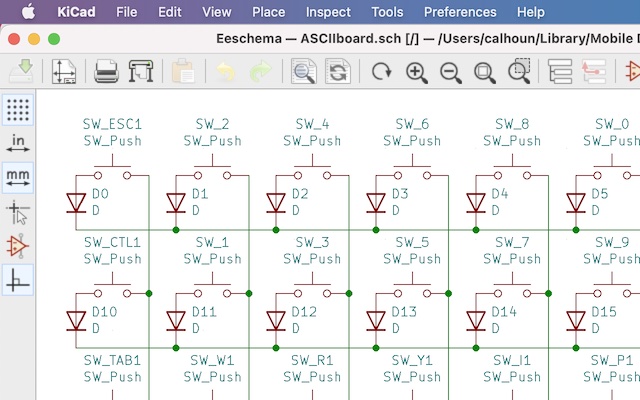
Just a note regarding the above schematic: there’s those diodes connecting each switch to it’s coresponding row.
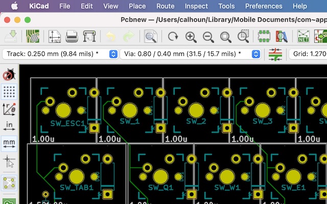
Something that I was anxious about going into this was how I would determine the size and placement of every hole and throughhole for the keyboard switches — never mind the spacing between the keyswitches. Imagine finding your expensive PCBs arrive from China and the switches are too close together to put the keycaps on.
Thankfully some kind soul has already carefully specified the dimensions of the standard Cherry MX keyswitch and made them available as a KiCad footprint library you can easily import into KiCad.
You can see the footprints in the above image. The solid yellow circles are the drilled holes for the mechanical portion of the switches. The light grey boxes (labeled 1.00u) indicate the size of the physical keycap on the board. There are different sizes for wider keys, spacebars. The larger keys that require stabilizers also have drill holes placed for the stabilizers as well.
Thank god for kind internet strangers.
I should point out that the Cherry MX is a fairly standard keyswitch footprint. The Gaterons I ended up getting fit the same holes, are the same size. But there are two flavors of key switches — those meant to be installed in plates and those meant to be installed in PCB’s (often referred to as 5-pin switches). Get the right ones.
The final step in creating a PCB is to export the PCB as a folder of Gerber files, zip it up and upload to a site that will take the Gerber files and feed them into a machine that will cut the PCB, etch the copper, apply solder mask, silkscreen and drill the holes. The first place I tried gave me an online quote in the hundreds (!) of dollars. I kept looking.
The second place I tried was PCBWay. I am new to this so can’t tell you the best site. But PCBWay quoted me less than $100.
Something that surpised me: after uploading the Gerber files I got stuck on a screen unable to proceed, unable to pay for the order. What was this? Was it a problem with their site and me browser? No, you simply have to wait for them to come back and approve your order. I can’t say exactly what that might entail but for me it took nearly an hour (as I recall) but then I was able to pay and place my order.
To my surprise, the 5 boards (minimum order) arrived a week later. All the way from China.
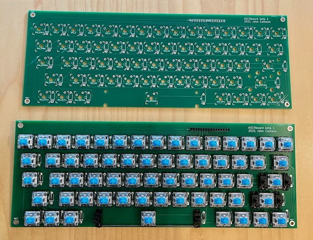
Two of the boards are pictured above: one bare and one “stuffed”.
Let me tell you something else interesting about this experience: the final layout of the PCB and the placement of my order through PCBWay took place from a van while I was on the road, camped in the desert with my wife in Arizona. During the day, driving, hiking, exploring, visiting museums. Evening and we’re settled into a state park somewhere reading or dorking around on our laptops. What a fascinating world we live in.
After soldering 124 switch pins, 124 diode leads, and a 16 pin header, I finished with the stabilizers and keycaps. The Teensy and breadoard still hang off of the keyboard (I intend to put the controller on a daughter board) but it still feels like progress.
Also arriving on the breadboard: a 74HC595 shift register. While I was careful to conserve GPIO pins, 7 pins for ASCII and an 8th for the strobe would leave me no more easy-to-access pins on this Teensy. And what if I want a pin to turn on/off a capslock LED? Or another pin to act as a negative parity bit for the 7 ASCII bits?
So I made the decision to add the shift register. It will require 3 pins to drive but can represent the 7 ASCII pins as well as a parity bit. Even tossing in another GPIO pin to drive a capslock LED leaves us with 4 remaining GPIO pins.
Engineers like to have a few extra pins for future expansion.
Daughterboard
I created a daughterboard in KiCad the same way I had created one for the keyboard. I wanted to create a PCB to replace all that crap you see above on the breadboard — spaghetti wire running to the keyboard header.
I didn’t really want to have a daughterboard — would rather have a single PCB for the entire keyboard. But the keyboard PCB is already so large, you hate to extend it in order to add the controller chip(s). To be sure, I have seen commercial keyboard PCBs that manage to squeeze a tiny SMD microcontroller in between the key switches, but I’m a hobbyist, not a robot.
After studying the pinouts of the Teensy 3.2 and the Teensy LC I decided to go for it — drop in a Teensy LC rather than the originally planned Teensy 3.2. It absolutely worked.
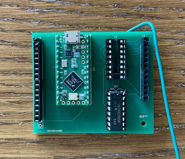
For this first itteration of the daughterboard I was not concerned with layout — like where the USB cable exited, where the daughterboard was in relation to the keyboard PCB… and clearly this is all screwed up. I was only conerned with making the layout of the traces on the PCB straightforward.
Something you can see in the photo above, I bodged a few extra wires on to experiment with a Caps Lock LED on the keyboard. The flying wires connect to a convenient ground pin and an extra GPIO from the Teensy LC. They run to an LED + resistor that I simply bent around the edge of the keyboard PCB (underneath the capslock key cap) and held fast with double-sticky foam tape.
Firmware
I believe I started with this teensy-thumb-keyboard code. I like it a lot. It has a clean keyboard matrix scanning implementation (in C++, FWIW) and the “main” code in an Arduino file (Teensyduino in this case).
I removed a lot of the debugging code (it was useful but distracting). I also ripped out a lot of the specialty code for using the keyboard as a mouse and the code for controlling things like brightness with the keyboard. I suppose I could add it back in if it seems useful. At this point I’m tending toward bare-bones.
I added, of course, code to output ASCII to the shift register (and strobe). I also added code to handle capslock for the ASCII output.
I left in the rest of the code that output the keycodes over USB.
When I had compiled and installed the keyboard firmware to the Teensy, right away the keyboard was recognized as a USB keyboard by Mac OS. I was typing, Copy/Pasting, using modifiers with the cursor keys to select text, …