Quarter-Cab (Phase I)
Playing virtual pinball has been such a blast with a cabinet that I wanted as many people to be able to experience it as possible. I understand though that the cost can be prohibitive and that many people have had no experience working with wood.
So I set about trying to come up with something of a minimal virtual pinball controller that, although not an actual cabinet, would be fairly easy to construct and get you a lot of the fun of a cabinet. Furthermore, in terms of cost, I wanted an affordable version — let’s call it Phase I. It would have the flipper buttons, other buttons, but little else. Then a Phase II would extend the original cabinet by adding support for surround-sound feedback (SSF) — but of course cost a little more.
Form Factor
This is not a full-size pinball cabinet by any means. That was not what I was aiming for. I started out thinking it would instead be a small slab-like thing you can set on your desk in front of the PC — something more like a thick keyboard. Cleveland Software Design sells something like what I was imagining. But it too wasn’t quite right. It is not “regulation width” and it can not be upgraded for SSF (surround-sound feedback).
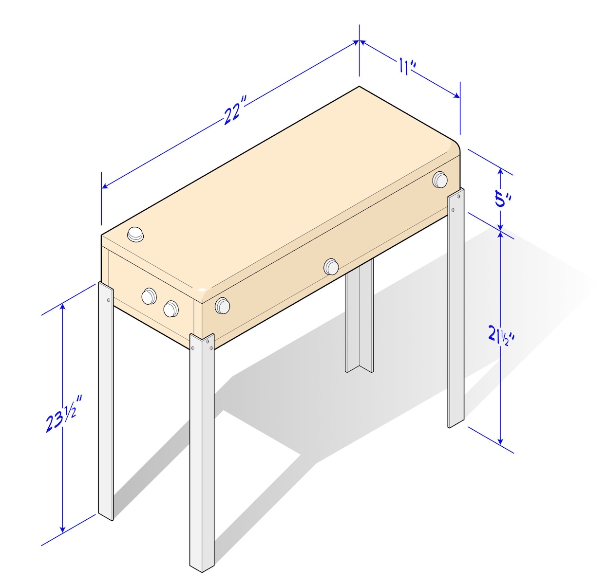
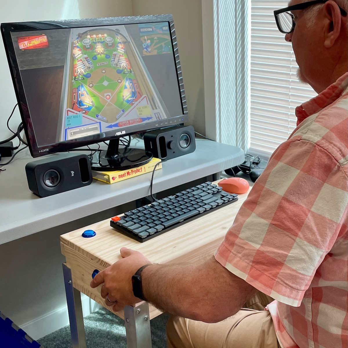
What I came up with I call a “quarter-cab”. It shares the width of a full-size pinball cabinet but is only about a foot deep. It’s not too big but still roomy enough to later add transducers and amplifiers if we end up going on to Phase II. Rather than slapping it on the desk in front of me, I found putting legs on it and propping it up in front of the PC allowed me to put my hands/wrists in a more authentic position and allowed me to nudge the cabinet.
Oh yeah, even Phase I will allow you to nudge the virtual pinball table.
Cost
It’s hard to nail down the cost of a project. It can climb if you need to buy tools — for example, a 1-1/8" Forstner bit (for drilling) is almost a requirement for making the holes for the buttons. If you don’t already have one and can’t borrow one, that’s another $11 or so.
Paint and screws? You may have something already on hand.
I’ll lay out the stuff you almost certainly will need to purchase below. But keep in mind costs could rise if there are a few tools and smaller items like screws that you need to purchase.
Prices don’t include shipping, tax. Prices may of course vary.
From Cleveland Software Design:
• 8× LED Leaf Button - 5V, JST Terminal: ($2.50 each, total: $20)
• 1× PinOne Control Board ($40)
• 2× JST Terminal Button Extension Cables (4 included, $2 each, total: $2)
From Amazon or eBay, etc.:
• 1× 20cm Ribbon Cable Male to Female ($7)
• 1× Double Row Screw Terminal Strip Blocks ($11)
• 1× PCB Mounting Feet L-Shaped (20 included, $7)
From a big-box hardware store:
• 1× 4' × 16" Edge-Glued Pine Panel ($16)
• 1× Aluminum Solid Angle., 1-1/2" × 6' ($25)
Total: $128
The most expensive part above is the PinOne Control Board from Cleveland Software Design for $40. It’s not an unfair price though. The USB controller that is typically recommended is the KL25Z. If you can find one you are unlikely to find it for less than $40. Typically too they go for over $100 on eBay since they seem to have become un-obtainium. Either will work though. Both have a built-in accelerometer in addition to pins for the input switches (buttons). Both have nice software front-ends that make them easy to configure.
Cleveland Software Design make an interesting “carrier board” for their PinOne called the PinOne Mini Virtual Pinball Connection Board . If you get the option without the Power Boards, it’s $25. I have not yet purchased one to test out, but it looks like, on paper at least, that it would make wiring the Quarter-Cab a good deal simpler. It may also mean you do not need the Ribbon Cable or Double Row Screw Terminal Strip Blocks from above. That makes it only an additional $8. If I try it out and prefer it I will update this post. If you feel like experimenting yourself, by all means give it a try.
The USB I/O board really is the “brains” of the virtual pinball controller. You need a way for the flipper buttons to talk to the PC and the added bonus of a built-in accelerometer means you get table-nudge for free.
The wood is the next most expensive item. By all means if you have 3/4" thick sheet-style wood lying around use it. Maybe someone will find an IKEA cabinet that is perfect to use for a Quarter-Cab. The edge-glued panel I suggested will only barely suffice in terms of size. (In fact there is a slight opening in the back of my cabinet because I was a few inches shy of getting all the parts cut from the 4' × 16" panel.) If you thought you could make use of left-over wood, a 6' long or 24" wide panel will give you more than enough for the Quarter-Cab.
Next most expensive is the angle aluminum for the legs. If you have something else or find something cheaper, go for it. I found wood, unless you go with 2×2 framing lumber, was going to be close to the price of the aluminum. And when I considered that the angle aluminum kind of resembles actual pinball cabinet legs, I had to splurge.
The leaf buttons you might be able to find somewhere else cheaper. But I’m already in for the shipping cost at Cleveland Software Design so I figured why not add their buttons to the cart. And the extension cables turned out to come in handy as well.
The other odd things: terminals strips and ribbon cables, are there to make wiring the cabinet neat and easy, require no soldering. I did not list these, but cable ties or tie-downs will also make the wiring a little neater in the cabinet. These can be picked up from your local big-box home center store (electrical department).
Wood Layout
As a purist, I’m going to suggest that the only real critical dimension of the Quarter-Cab is the width: 22". I think it is critical because it is the standard width of most pinball cabinets and I want the realism (there is also a wide cabinet standard but for purposes of the Quarter-Cab, smaller is better).
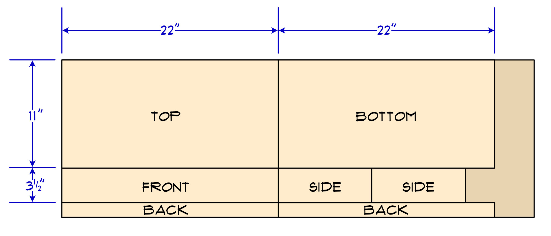
The top and bottom piece then are 22" long and 11" wide. The 11" depth of the cabinet was chosen because I could get it and the sides out of a 16" wide panel and it allowed enough room inside to eventually add transducers and amplifiers for SSF support (surround-sound feedback). You could try a little less than 11" if you later try to crowd things in. Of course as a kind of table thing, the Quarter-Cab will likely fall over all the time if you make it too skinny.
The front and back pieces are also 22" wide to match the top and bottom. The back piece though was the one I was not able to get out of the 4' × 16" panel as a single piece. If you go with a 24" wide panel or a 6' long one, you will have more extra wood left over but you can then make a rear piece identical to the front one (3-1/2" × 22").
The front, rear and sides are all 3-1/2" wide. Because saw blades have thickness, you’re going to be left with less than 1-1/2" for the width of the back pieces.
If wood panels were exactly 3/4" of an inch thick then the length of the two side pieces could be calculated to be exactly 1-1/2" from 11" (so 9-1/2"). But wood panels are often 1/16" of an inch or so thinner than 3/4". So you may need to add about 1/8" to the length of the sides. One way to determine the length of the side is to, once you’ve cut the pieces, measure the thickness of two pieces stacked up and subtract that from 11". If you’re not sure though then just cut each side 9-5/8" long — that’s going to be pretty close.
Wood Cutting
There are so many ways to cut the parts of the cabinet from this panel — which method you choose depends on the tools you have available or, if you will have to get a saw, it will depend on how much you want to spend, how much use you expect to get from your saw, how danger-averse you are, how important fit and finish are to you, etc.
At one end of the spectrum, using a hand saw to cut the panel is do-able. The long cuts with the grain of the wood (the rip cuts) are going to be a challenge to keep straight. If you’re into hand tools though a hand plane will probably clean the edges up after ripping them with the saw.
I chose pine specifically because of how soft the wood is — how easy it is to both cut and sand. You can of course use any kind of wood you like for this project but if you are new to wood-working I think you will appreciate how easy pine is to work with.
A circular saw without some kind of guide or track may be the most challenging for the long rip cuts. A fairly inexpensive track saw though would be a really nice tool to own. I don’t think of track saws as being as dangerous as a table saw and they certainly take up less space and are less expensive. I recommend track saws to new woodworkers.
A fairly thick sheet of foam insulation board gives you a nice surface to put the wood down on when using a track saw so that you have a sacrificial surface to take the blade that extends past through the wood when cutting. A few clamps can hold the track in place while you make the longer cuts.
A table saw is of course the most precise way to cut the pieces out — especially the long rip cuts.
Maybe you know someone with a table saw that can help you out. I see five or six cuts in total to take this panel down into the parts needed to construct the Quarter-Cab.
Don’t let me stop you if you’re comfortable with woodworking and want to take this to the next level with fancy joinery. The dimensions above are for simple butted corner joints. I think you can do the math to figure out how to adjust the dimensions to allow for finger joints, miter joints, etc.
Glue-up
There was a time when I would have proceeded to nail together the parts of the cabinet. And you can go that route if you like. Some time later, probably after watching too much New Yankee Workshop, I might have used a pneumatic pin-nailer to put together the box.
Increasingly I have been moving away from metal fasteners completely — relying on dowels, glues. For this project I went with just straight Gorilla Glue. It holds very well when it has set up and there are no nails or other metal things you have to worry about accidentally hitting when sanding or with the drill when you go to add the buttons.
I am referring to the original, polyurethane-based Gorilla Glue — they have all manner of glues now — their wood glue would probably be fine too though. But if you do go the wood glue route I have always used Titebond III.
One down-side of only using glue is that you need some means to hold the parts in place while the glue dries. I have enough clamps to do the job. Someone clever with less clamps might be able to figure out a way to do it with weights sitting on the parts to hold them still and pressed against one another. Even with clamps though, another down-side to using glue only is that you have to assemble the cabinet in stages, waiting for the clamped parts to dry before assembling more of it together.
If you don’t have clamps, a compromise would be to still glue it up, but use a very minimal number of finishing nails to hold it together until the glue dries. This would probably allow you to do the entire assembly in one session.
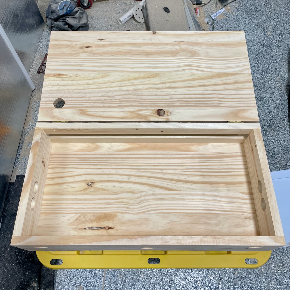
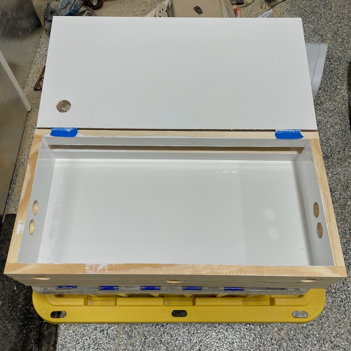
It is important to point out though that the top of the Quarter-Cab is not glued on. It acts as a lid and will be hinged at the rear allowing easy access to the inside of the cabinet when you need to. The sides, front, rear and bottom are all glued to one another.
Hinges and Holes
Whether you attach the lid with hinges next or drill the holes for the buttons next, the order is unimportant. After assembly you’re going to want to use two small hinges to attach the top piece of the Quarter-Cab to the rest of the carcass. Taping the lid on with painter’s tape is one way to hold it in place while you align the hinges.
Use a pencil to circle the holes in the hinge where you will put screws into the wood. You can then use a punch or a small nail to make a small indentation to guide the drill. A small 3/32" drill bit will make a nice pilot hole in the wood making mounting the hinges accurate and easy to do with a simple screwdriver.
The Quarter-Cab has a pretty minimal design with regard to cabinet buttons — just eight of them.
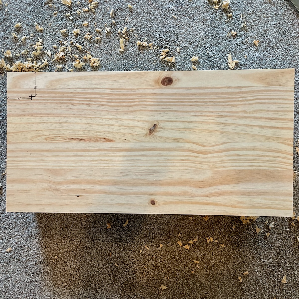
Let’s start with drilling holes for the pair of buttons on each side of the Quarter-Cab. These are the left and right flipper buttons as well as an extra “magna-save” button for each side.
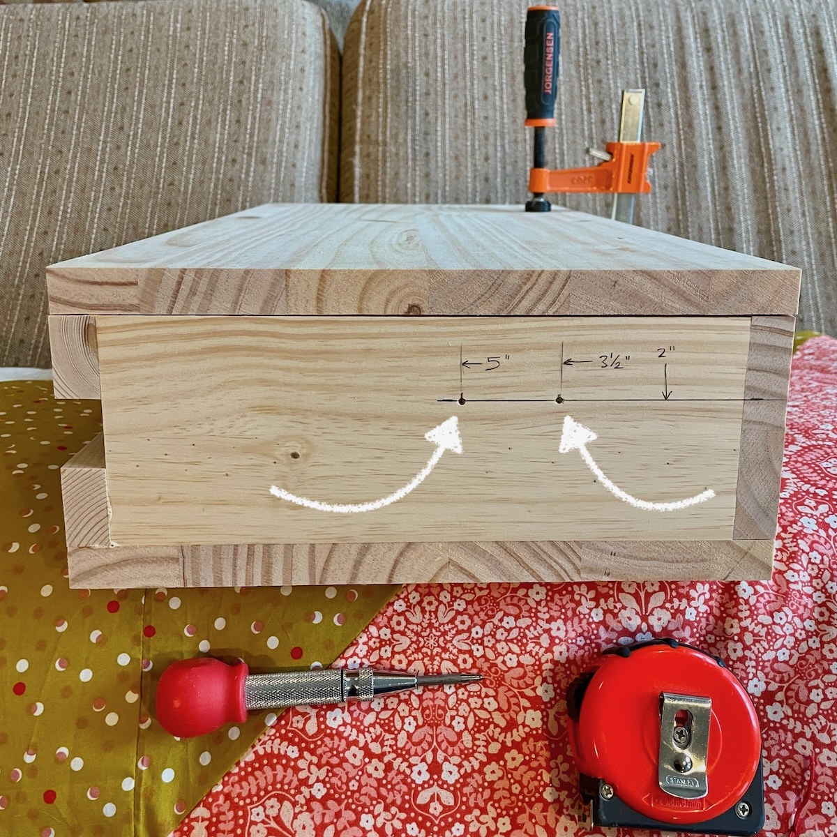
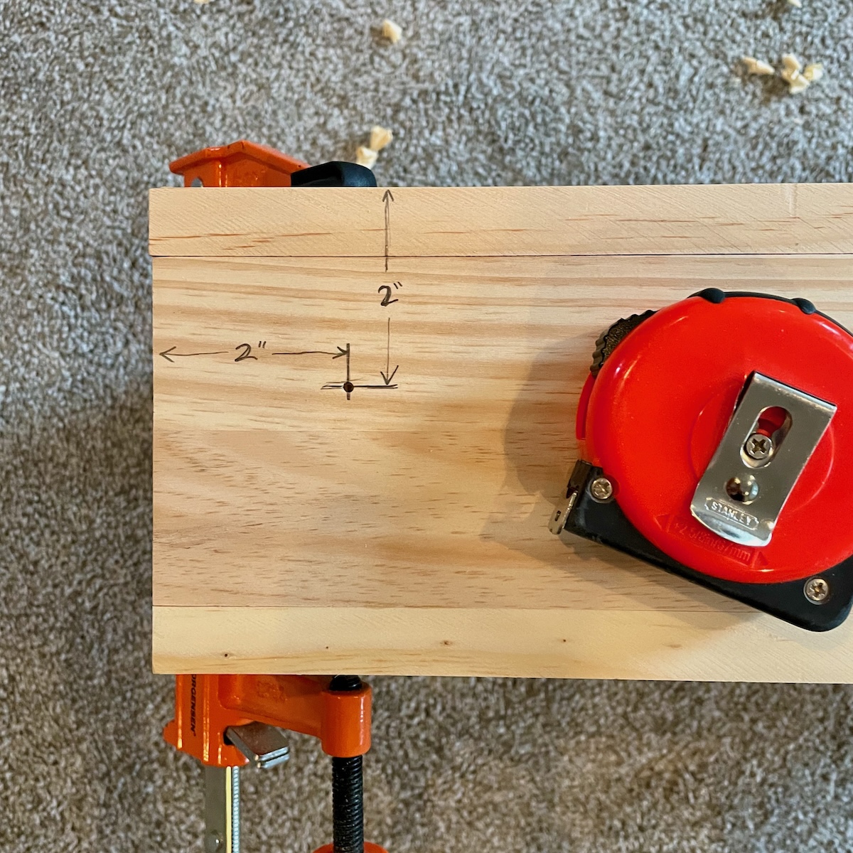
The photo above is of the left side of the Quarter-Cab. I know because you can see the rear of the cabinet is on the left (recall it had to be made with two pieces of wood — you can see gap between them). The thing to pay attention to is that I am now measuring starting from the front of the cabinet to position the centers of the two holes — one each for the flipper and magna-save buttons.
I am also measuring down from the top (with top lid in place). When you place the holes on the right side of the cabinet for the right flipper and magna-save buttons, be sure to also make your measurements from the front of the cabinet and down from the top.
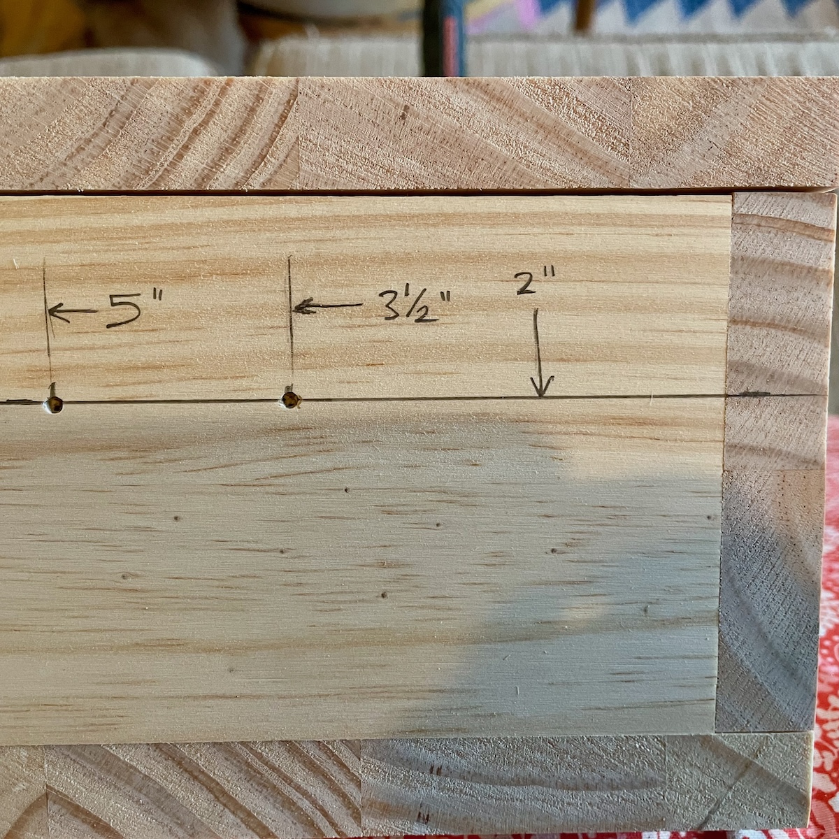
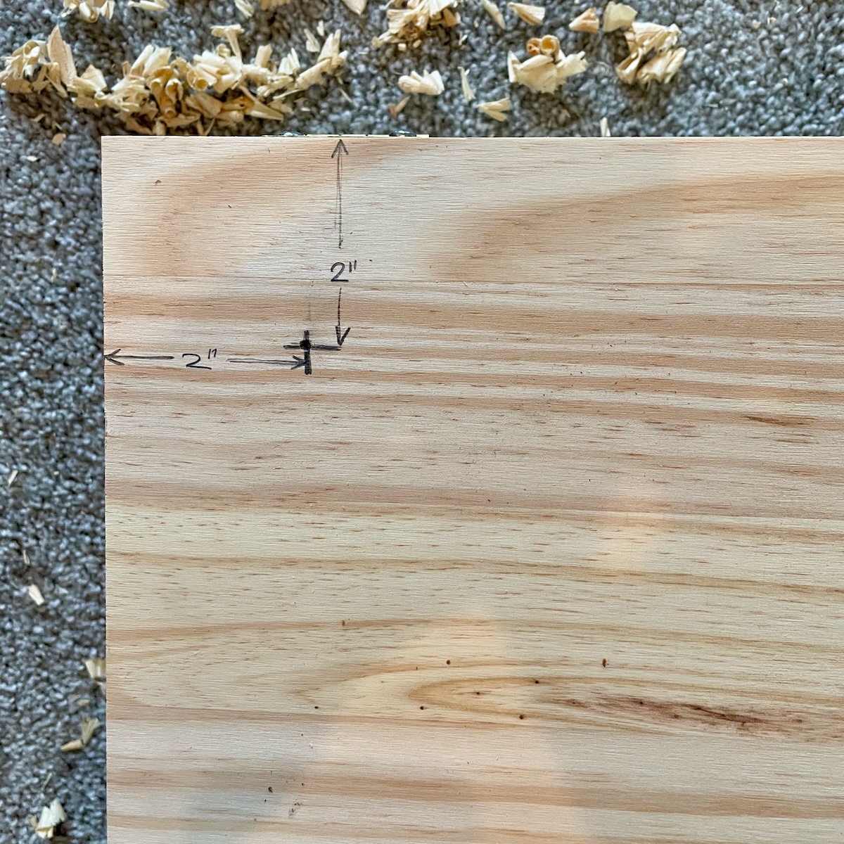
What the photo is showing is that you come down 2" from the top of the cabinet for both buttons (this is with the top of the Quarter-Cab in place). The flipper button then is 3-1/2" back from the front edge and the magna-save button is 5" back from the front edge of the cabinet (that leaves 1-1/2" of space between these two buttons).
Use a punch or a nail to mark the centers of these holes so that the drill has a pilot hole to ensure it stays centered. Then pre-drill these holes all the way through the wood with a small 3/32" bit.
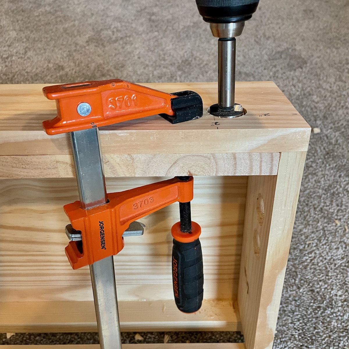
With a pilot hole drilled, I switched my drill up to use a 1-1/8" Forstner bit. A spade bit is not going to give you a nice enough hole. You could go with a hole saw, but a Forstner bit, in the end, is going to give you the best results. 1-1/8" is kind of an odd sized bit. You’re unlikely to find someone you can borrow one from and may have to buy one. If it is any consolation, I bought one decades ago and have used it on many gaming projects like this one. (MAME cabinets, for example.)
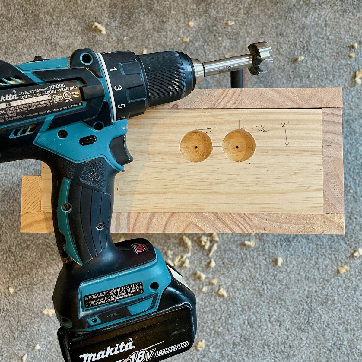
Above I stopped drilling when I was roughly half-way through the wood. The reason was that I wanted to minimize the tear-out that you can get when a drill bit, especially a large one like this, breaks through to the other side of the wood. Having drilled a pilot hole first, I can stop half-way and continue drilling the hole from the inside of the cabinet. When the two holes meet from either side there will be no visible tearing.
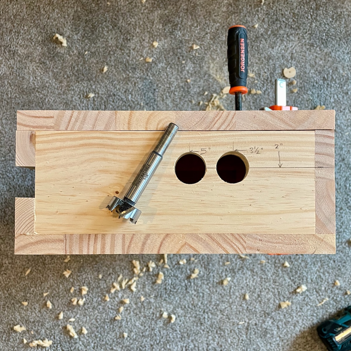
The results speak for themselves. I have two very clean holes for installing buttons in. And don’t worry about the pencil marks, we’ll probably sand them completely away when we get to finishing the Quarter-Cab.
After having successfully drilled this pair of holes, go do the same on the other side, being mindful of course that they are in the right location relative to the top and front of the cabinet.
Front Holes
I have included only three buttons on the front of the cabinet: a button on the left for starting a game, a button in the center for adding credits to the game and a button on the right to act as the plunger.
If a real mechanical plunger is important you can find online how to go that route. It should fit in this cabinet and I am not 100% sure but the PinOne may natively support it (or may need a daughter board to support it). I have avoided going with a real plunger simply because of how fragile they appear to me — not the mechanical parts but rather the potentiometer attached that repeatedly gets yanked by the plunger spring.
Drilling the holes for these buttons is the same as the holes in the side. I’ll give you the measurements and some tips.
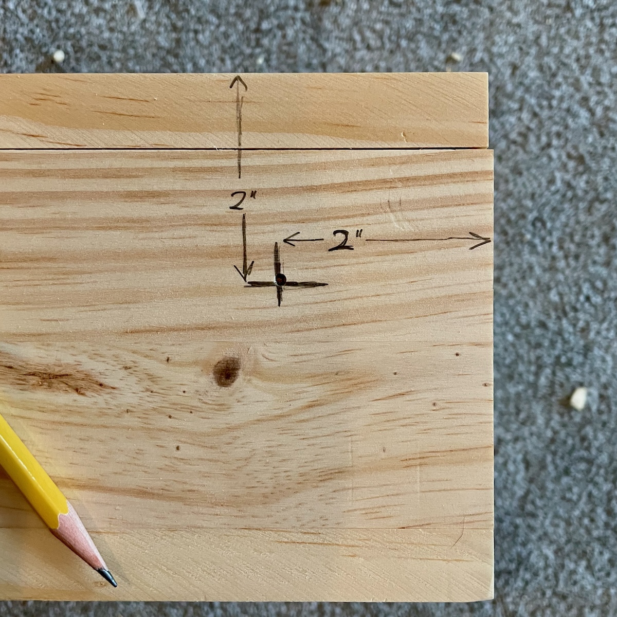
The hole for the Start button is on the left-hand side of the Quarter-Cab when you are in front of it. The center of the hole is 2" down from the top of the cabinet (with the lid or top on) and 2" from the left side.
For the previous holes I was able to drill half-way from the outside and then finish up from the inside. There is not a lot of room for these from holes to get a drill inside the cabinet and drill forward. You might instead go ahead and drill all the way through from the outside but try to clamp a piece of sacrificial scrap wood behind where you are drilling so that the drill doesn’t make a jagged exit wound when it makes it through the front of the cabinet.
Use this trick for the other two holes in front.
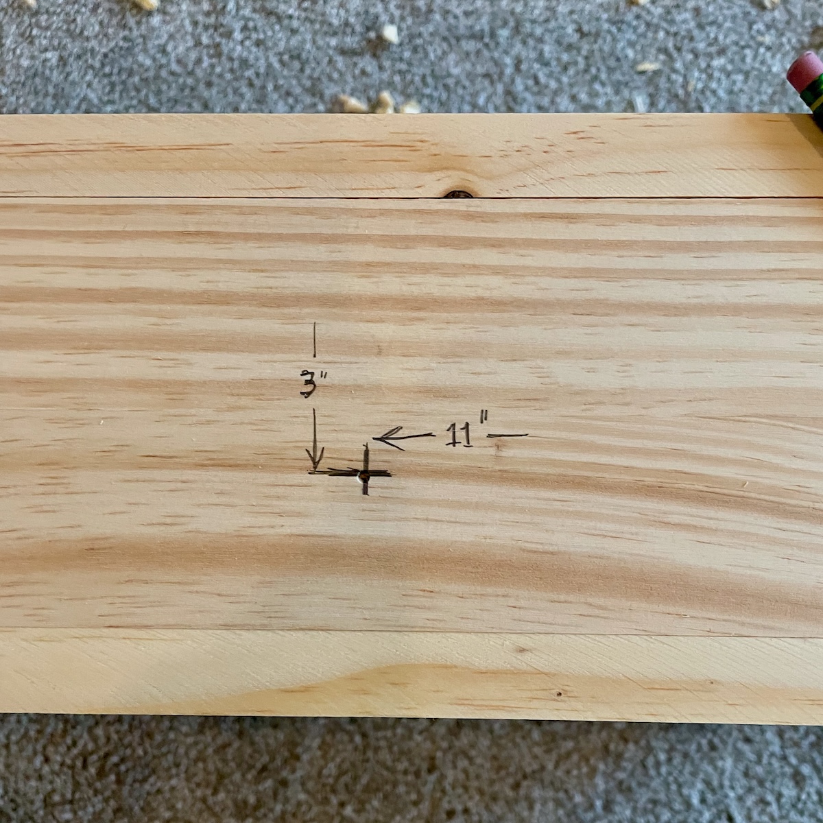
The hole for the Coin button is right in the center of the cabinet, but close to the bottom (where a coin door is located). I measured 3" down from the top (including lid) and 11" from either side should put you right in the center.
The hole for the plunger button is symmetrical to the one for the Start button. 2" from the right side, and 2" down from the top.
Final Hole
The last hole we need to drill is for the “Exit” button. I put it on the top of the cabinet (on the lid) but back near the rear and off to the left. I want to keep someone from hitting it on accident when they meant to hit the Start button for example. I also wanted to leave the top more or less clear though so you can put a keyboard and mouse on top if you like.
It is 2" from the left edge of the top and 2" from the rear edge of the top. This hole is easy to drill half-way through from the outside and then finishing the hole by drilling from the inside.
All the holes are drilled, the cabinet is ready for finishing (and then we will start installing the hardware).
Painting
I don’t often paint the inside of a project, but I did for this one. Phase II of the Quarter-Cab will have some transducers that attach only with sticky-backed pads. I felt the bare wood would not be a good enough surface and a painted one would be an improvement.
You might get away with a number of coats of spray paint. The idea here is to get a good clean surface that is not as porous as wood. I happened to have a can of Rustoleum enamel paint and so went with that.
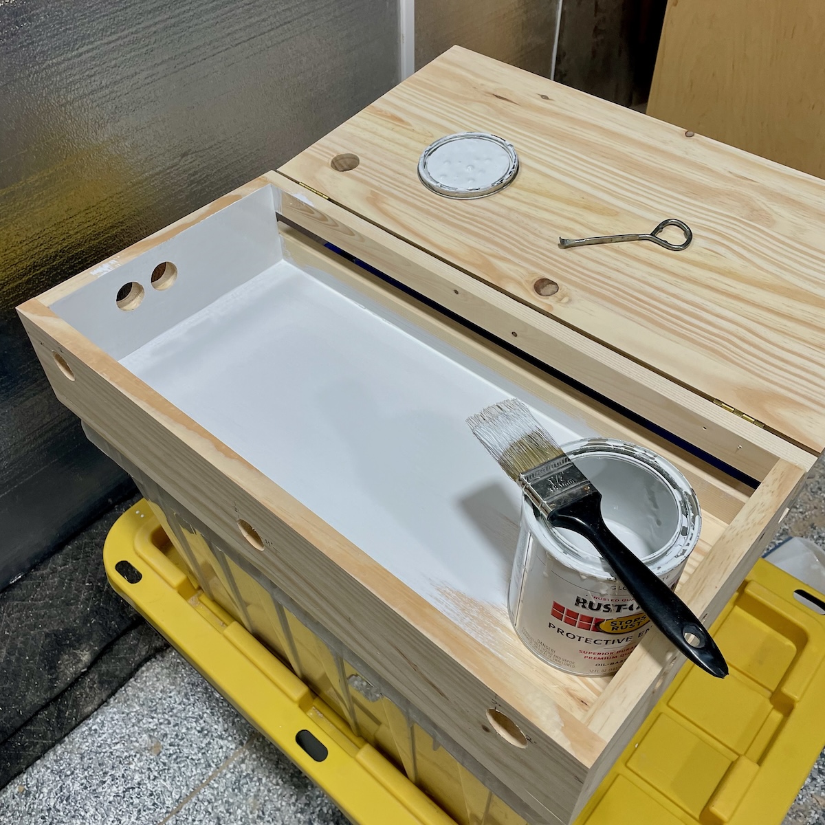
It’s a good idea to mask off the hinges (or remove them) to avoid getting paint on them. You might also mask the edges so that your paint stays in the area you want painted. If some paint gets “outside the lines” don’t fret it much. We are still going to sand the outside of the cabinet and can sand away a good deal of the overspray or overpaint.
It doesn’t have to be perfect, no one is likely to see the inside but you.
Sanding
Sanding is not optional for the two corners of the controller where you’ll rest your palms. Actual pinball machines have a metal piece called a lockdown bar that has nicely contoured, rounded corners to lay your hands on while pushing flipper buttons. Actual lockdown bars are pricey and we’re doing this on a budget, so we’ll have to content ourselves with smooth wood corners.
Fortunately since this is soft pine we can make short work of the corners. What you want to get are soft round corners that feel comfortable on your palms. I don’t know a precise way to convey the “roundedness” but it doesn’t have to be exact anyway, so you should just shape the corners until they feel comfortable to you.
Make sure the top (lid) is attached again and held down on the cabinet before you begin. There are a number of ways you can try to knock down the sharp corners closest to the holes for the flipper buttons.
If you have a belt sander or disc sander, that will take most of the corners off. When you have it close maybe you can move to a sheet of sandpaper and dial it in the rest of the way by hand. As I say, the pine is soft and you don’t want to go too far with an aggressive tool.
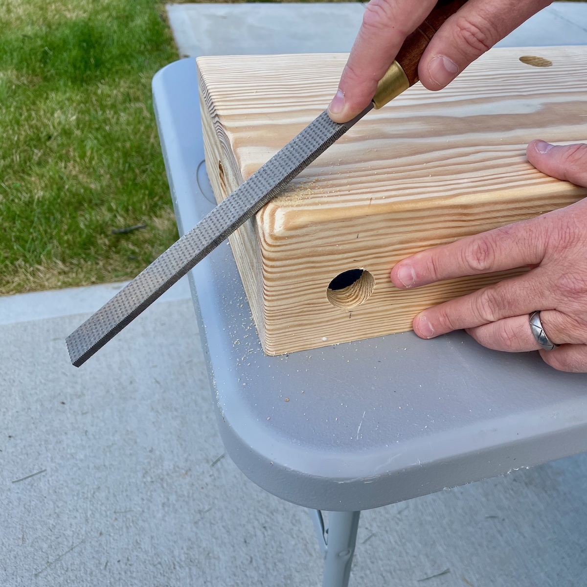
If you have one, wood rasps work good as well and are maybe easier to control, sculpt with.
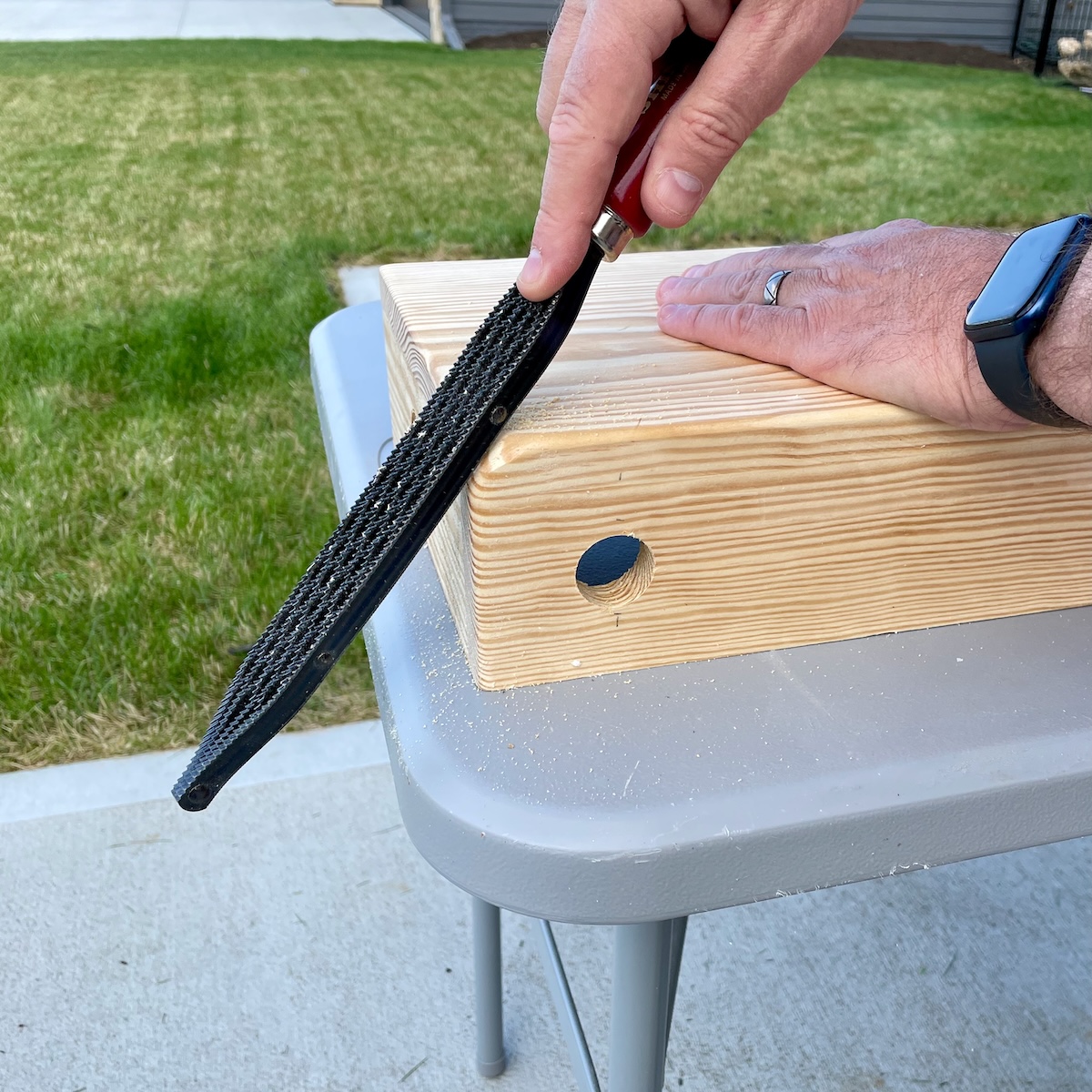
My favorite tool for this kind of work is the Shinto Saw Rasp — held like a hand file but looking like a criss-cross of hacksaw blades spot-welded together. It has a coarse, aggressive side and a little bit finer side to it. It will make quick work of the pine.
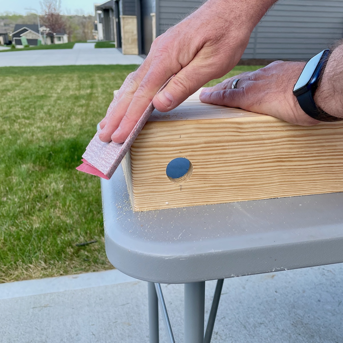
Although the corners near the flipper buttons are the most important parts to sand, feel free to round over any other edges you like, sand the surfaces smooth. This is also an opportunity to sand away any glue that might have oozed out and dried — and of course any paint you might not want. Or if some of your edges didn’t quite line up you might be able to bring them into flush with some sanding.
You should finish up by going over the whole cabinet with a fairly fine sandpaper, maybe 220 or 320 grit. An electric random-orbit sander is a wonderful tool to own and with a fine grit sandpaper can really clean up the cabinet. As I mentioned, any flaws, pencil marks, misaligned edged can be cleaned up in the sanding process.
Painting the Exterior
How you finish the outside of the cabinet is going to be a matter of taste. You can of course paint it like we did the interior. You can stain it and put on a clear finish but I have to say, trying to stain pine with a “walnut” stain (as an example) to make it magically look like a hardwood never succeeds. I say either paint it outright, or love pine for its warm glow and just put a clear or amber finish on it.
I decided on a glossy, clear polycrylic finish. Because I was lazy I got a spray can — that way I don’t have to clean another brush. (However, polycrylic finish is water-based so washes up pretty easily.)
When you are happy with the finish on your cabinet and have given it a day or so to fully dry, it’s time to start installing hardware.
Legs
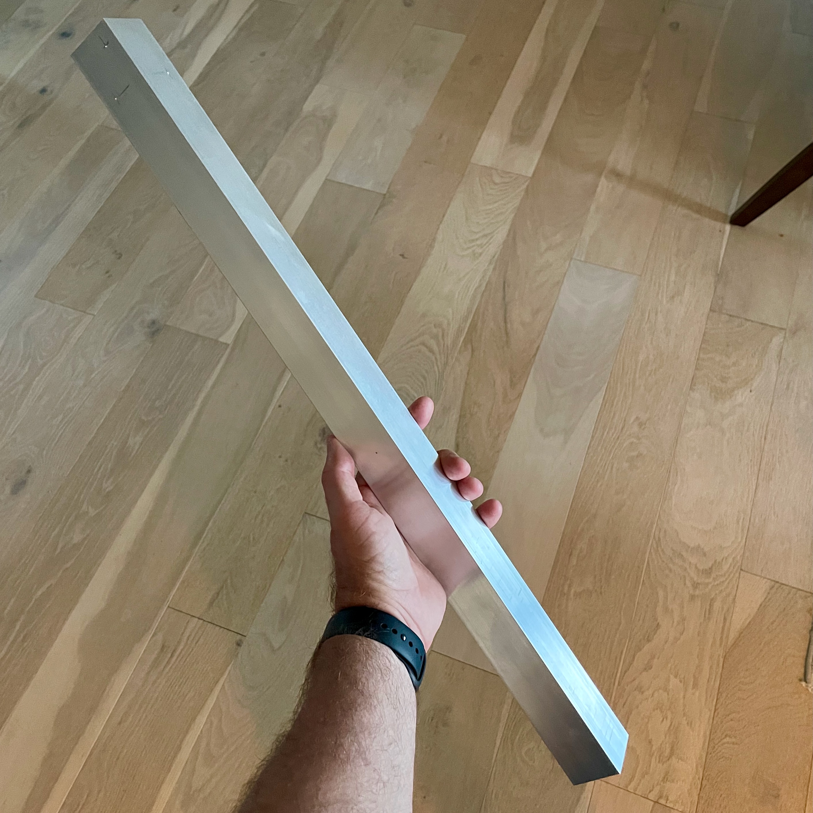
I was originally going to go with lengths of 2×2 wood for the legs — this I expected to be inexpensive. I suppose if I were content with framing lumber, it would have been the least expensive option. I looked instead at nicer-grade pine because I thought it made the controller look a little nicer. I was then surprised though to find that aluminum L-channel (8' in length) cost about the same — maybe even a little less than the nice pine. Since the L-channel actually kind of looks like pinball legs, it became the obvious choice.
An 8' foot length of the aluminum L-channel can of course be cut into four, twenty-four inch legs. When I sit in front of a computer desk the Quarter-Cab wants to be about 22" off the ground. That leaves 2" of overhang to attach the legs to the corners of the cabinet. Perfect.
I do a fair amount of woodworking as a hobbyist and, as far as I’m concerned, aluminum is just another hardwood. It is not difficult to saw, drill, sand. I’ve even routed it (but I would advise against trying to plane it). If all you have is a hacksaw, aluminum is soft and can be cut pretty easily. Make right-angle marks every 24" with a sharpie to act as a guide for sawing. If you have a miter box, you could try to use that with your hacksaw to get nice perpendicular cuts.
I have a table saw and I am comfortable using it to (carefully) cut aluminum.
I am going to strongly advise you to not use a “chop saw” or compound miter saw to cut aluminum. Because of the dsesign of the saw, the way the blade spins, it can violently either pull the saw into the piece or grab the aluminum and throw it toward you.
However you cut the aluminum, it is an easy metal to file so you can clean up your cut edges when you are done. Sanding works too. A coarse grit will act like a file but can leave scratches in the aluminum. A fine grit will clean up scratches and give you something like a brushed aluminum look.
Do not use the sandpaper that you use on aluminum on wood afterwards. The sandpaper gets dirty from the aluminum and will dirty your wood.
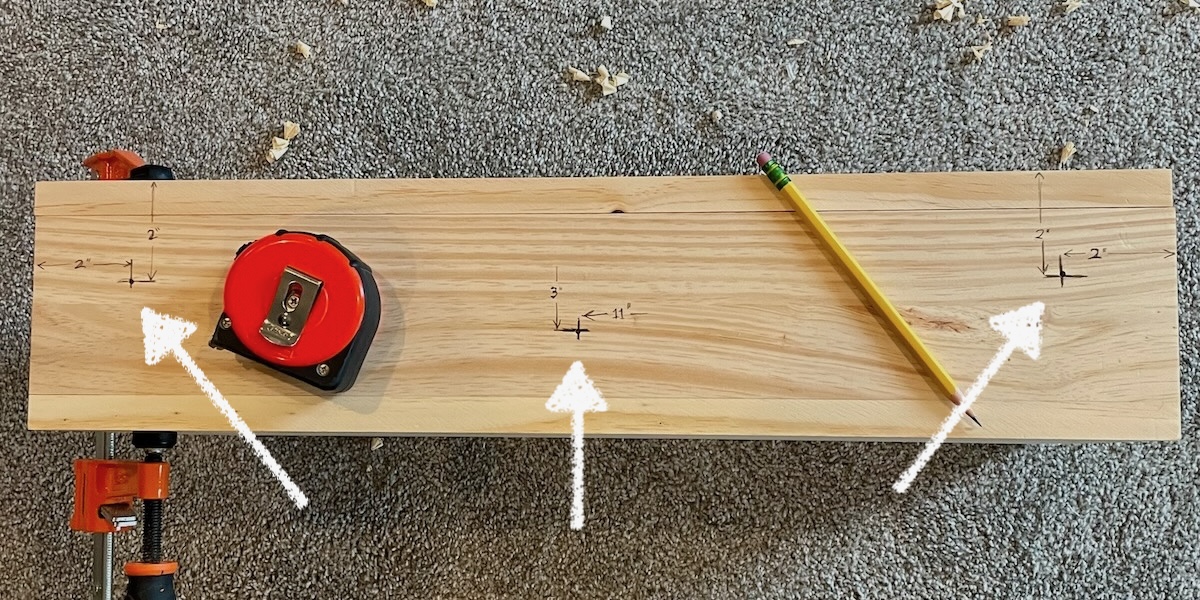
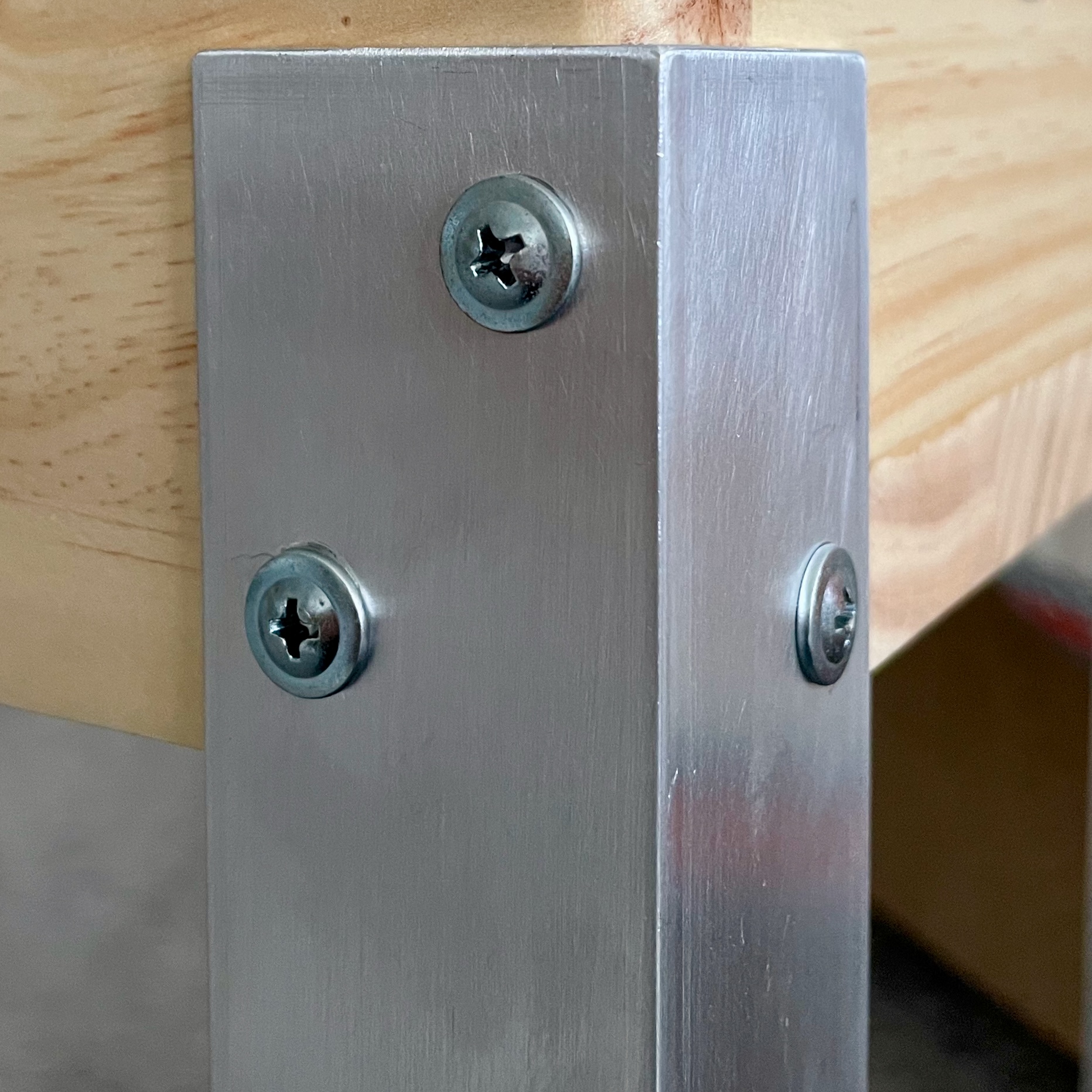
Allow 2" of the end of each aluminum leg to overlap the bottom corners of the cabinet. I used three long wood screws to secure each leg to a corner. Two holes were drilled 1-5/8" from the end of a leg, 3/8" in from the edges. A third hole was drilled 3/8" from the top-end of the leg, 1/2" from the edge where the angle meets.
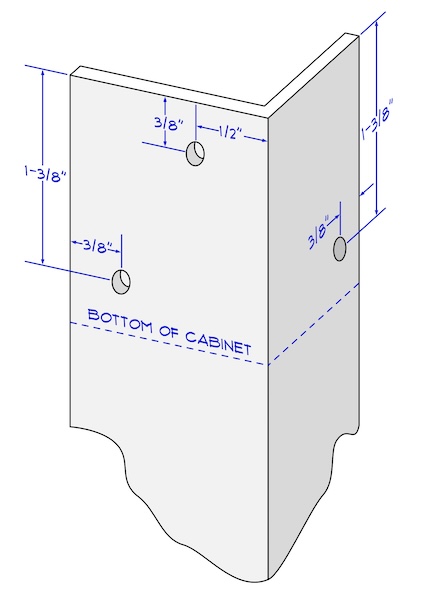
The idea was to place the screws in places where they could penetrate the cabinet over an inch or more without poking out the other side of the wood. So I made sure the screws were aligned with the boards, lengthwise. The two screws near the bottom of the cabinet hold the leg securely, the third screw, like a tripod, acts as a lever to keep the leg from folding in under the cabinet.
I used a 3/16" drill for the screw holes in the aluminum.
When finished drilling, align each leg, one at a time, at each corner of the cabinet. Allow 2" of the leg to extend alongside the cabinet and mark inside the holes with a pencil. Use a nail or punch in the center of each pencil mark and pre-drill a pilot hole.
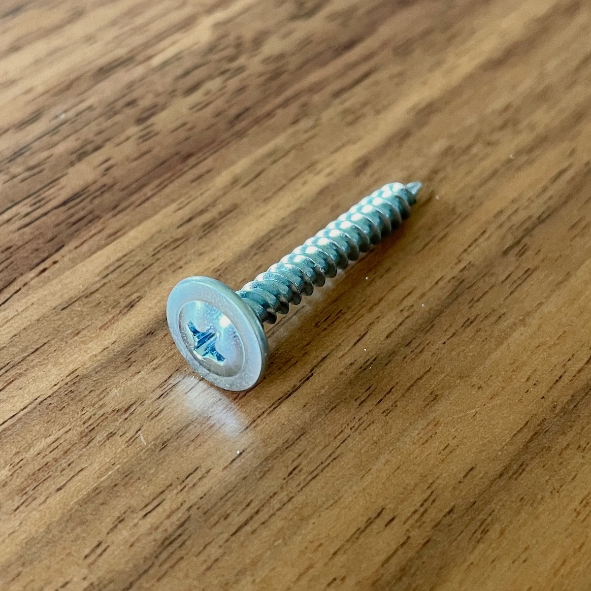
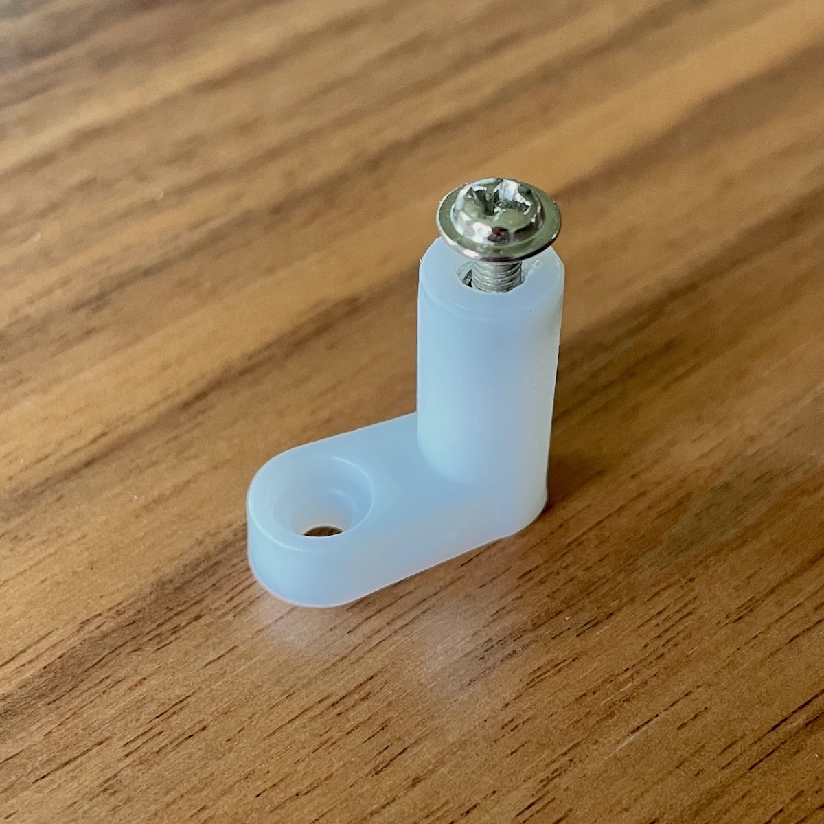
I am told these are called self-tapping washer-head sheet metal screws. They were 1-1/4" long and look like the photo. They have a nice flat head that acts as a washer. The threads are a coarse pitch and so work well in wood.
Attach the leg with wood screws at least 1" long.
Installing Switches
There really isn’t anything to say about installing the switches. The collar (nut) unscrews from the switch body, you insert the switch in a hole you drilled, and then thread the collar/nut on from the inside. To snug them up it is easier to twist the switch body for the final twist as there are small teeth in the collar that grip into the wood.
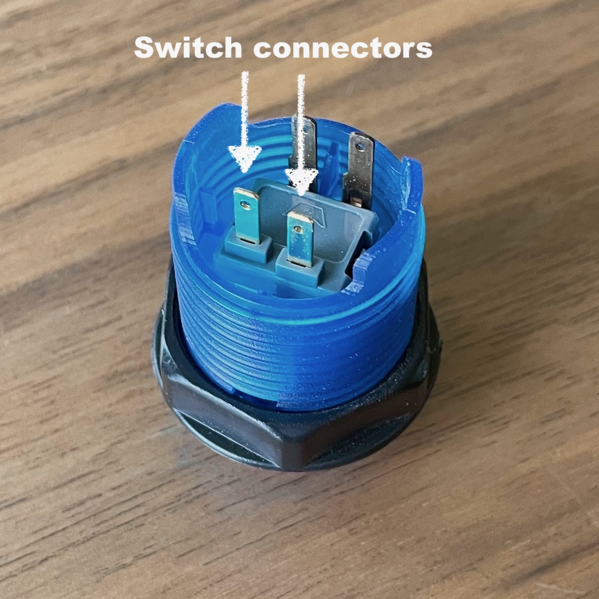
There are four pins in the switch body. Two of these are on a sort of dais on the switch body while the other two pins enter from the side. The two going straight down into the switch body are the two we connect for the switch action. The other two pins are for powering an LED in the switch if you should care to do that at some point.
Go ahead and install all eight switches. You get to choose what color goes where.
Installing the PinOne
The PinOne circuit board is screwed to L-shaped standoffs — the standoffs are then screwed to the inside of the cabinet.
I installed the PinOne in the rear of the box, more or less in between the coin button and the plunger button. The reason for placing it off-center was to leave room in the center of the cabinet for a bass shaker in Phase II.
The easiest way to position, mount these L-shaped brackets is to first install them on the four corners of the PinOne controller. Then place the PinOne in the cabinet in a position similar to where I show (it does not have to be exactly where I put it). Then, while holding it in place, go around and mark with a pencil where the L-Shaped brackets have their holes for screwing them down to the wood.
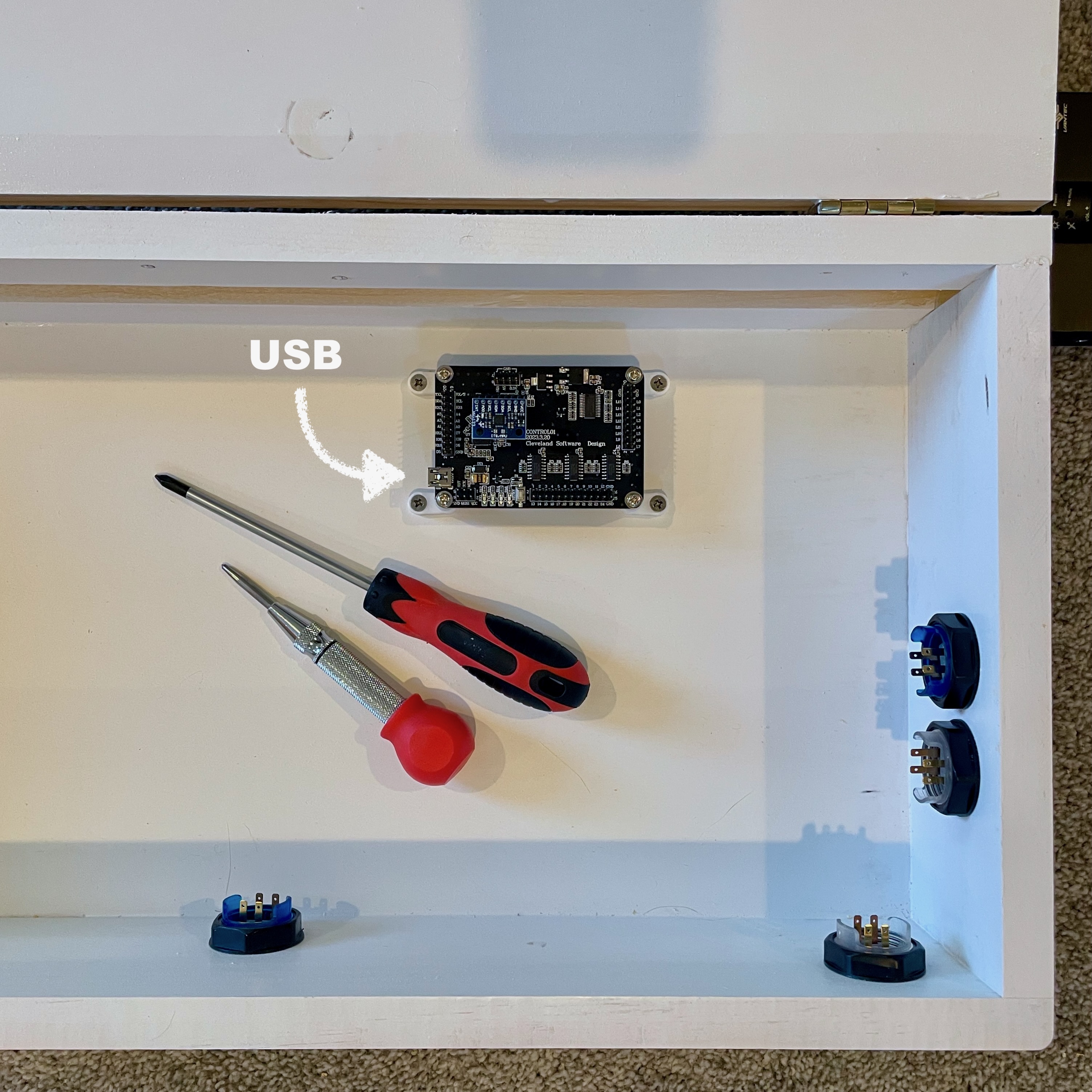
You’ll notice that I positioned the L-brackets so that they kick out lengthwise from the PinOne. Also notice that the USB socket that is soldered on the PinOne is to the left, facing the center of the Quarter-Cab.
Remove the PinOne so you can punch small holes where the pencil marks are. It’s a good idea to drill small pilot holes for the screws — of course take care not to drill all the way through the wood. (I usually, fold a small piece of masking tape on the drill bit to mark the depth I want to drill.)
I would suggest you remove the L-brackets from the PinOne before trying to screw them down to the cabinet. If you try to screw them down while attached to the PinOne I have seen a tendency for the L-brackets to twist with the screw and then twist the PinOne with them. If you screw them down by themselves first, you can straighten them out as need be to then mount the PinOne in position.
Terminal Blocks
To keep the wiring tidy, I found that a pair of screw-down terminal blocks works well. With these you should not need to solder anything.
The two terminal blocks are mounted running front to back inside the Quarter-Cab. They are near the coin button, which is to say close to the front of the cabinet, and they are each just on either side of the button. Be sure to leave some room for the wires to come out of the coin button.
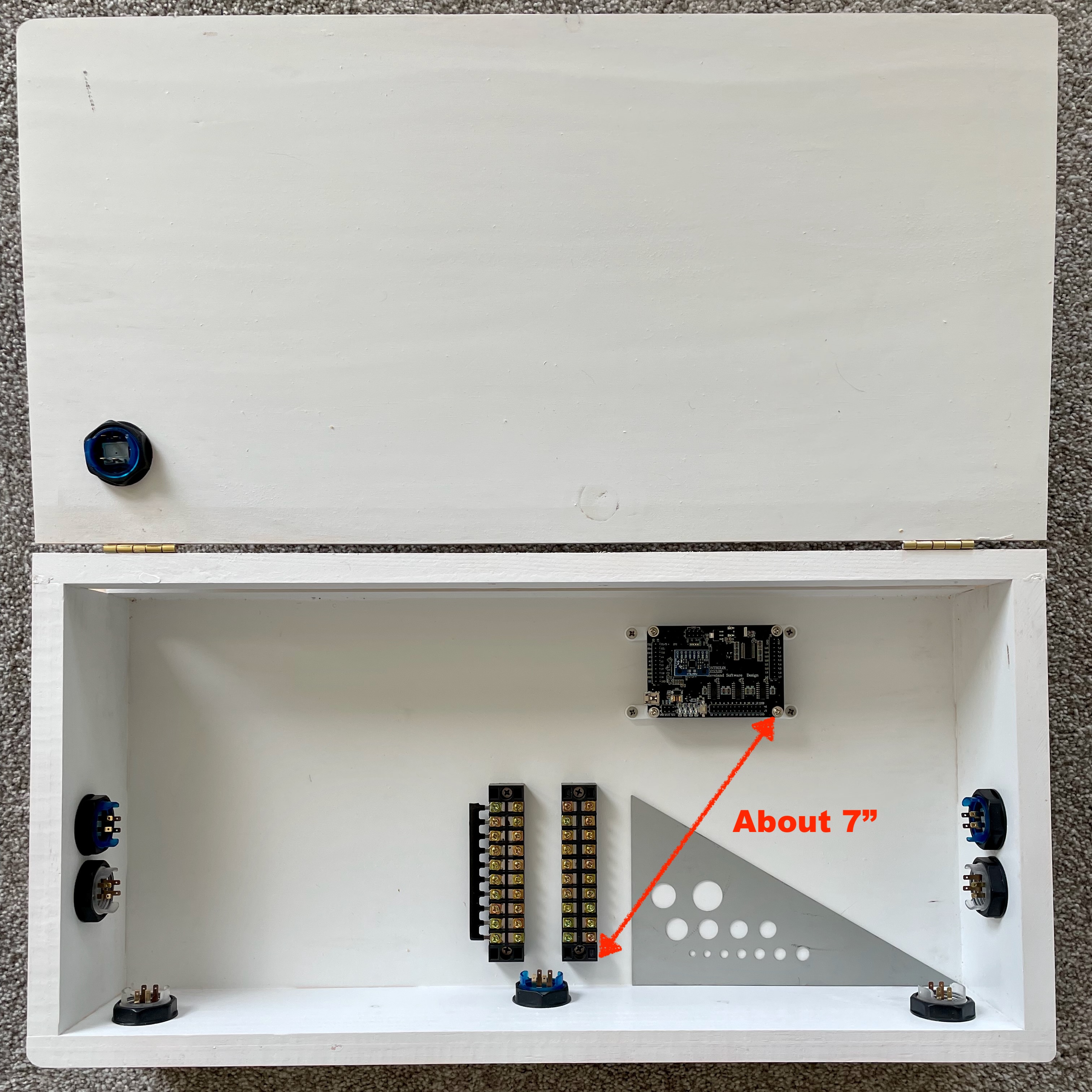
We’re going to soon run 8" wires between the PinOne and the terminal blocks. Try to make sure that the distance between the corner indicated on the PinOne and the corner indicated on the terminal block (closest to the PinOne) is 7" or less.
Each terminal block is held down with two wood screws. You can install these the same way you did with the L-brackets: mark the location of the screws with a pencil, punch, pre-drill, screw down.
The right terminal block is for joining one leg of all the switches to the inputs on the PinOne. The other terminal block will share a ground connection for all of those switches. The terminal block on the left is the common ground and that is why I have installed the metal bus bar strip on the outside row of pins. With the strip installed, any wire connected to a screw on the inside of the terminal strip will be connected to all the others.
Wiring the PinOne
It’s time to wire up the Quarter-Cab.
The PinOne might as well be called the PinEighty since it has about that many pins sticking out of the top of it. Fortunately we are only concerned with one row of pins.
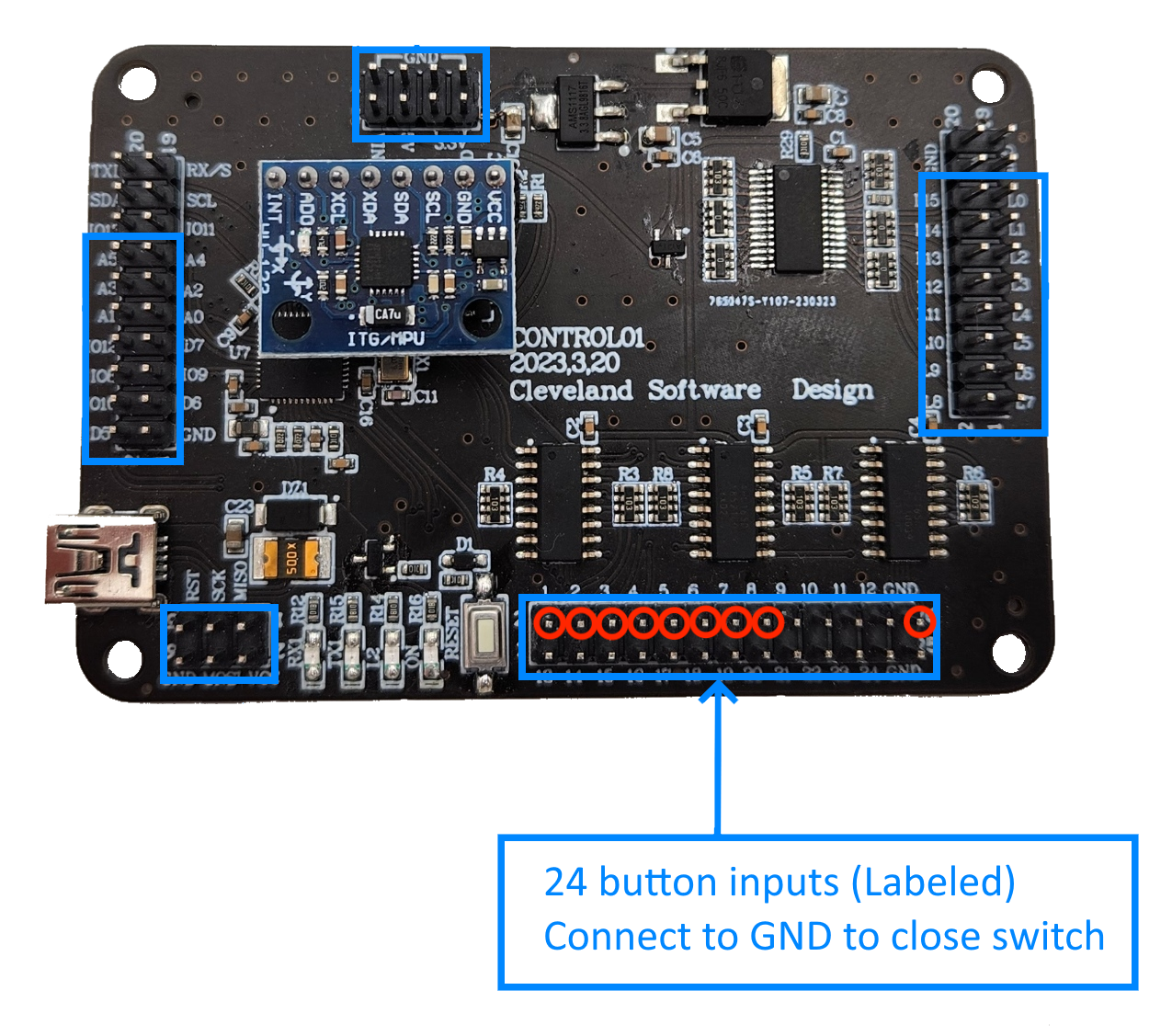
Orient yourself by locating the USB connector that is soldered onto the PinOne — in the diagram above it is on the lower left. The pins we want to connect our buttons to are in the two rows along the bottom edge of the board farthest from the USB connector. I have circled in red the specific pins we will use.
They are labeled 1 through 8 and then there is one hanging off the far right labeled GND (for Ground). You should know we have eight buttons to wire up to the PinOne and there are the pins 1 to 8. A button is just a switch. And for the PinOne, in order to detect if the button is pressed or not, you need to wire one end of the switch to one of the numbered pins, and the other end of the switch to Ground (GND).
Since all eight switches need a connection to Ground, one way to accomplish this is to “daisy-chain” a wire from one switch to the other so that they are all (indirectly) connected to the single GND. And you can wire up your cabinet that way.
But I prefer each button have it’s own ground connection and that is the reason for the left terminal strip we just installed — the one with the bus bar strip. In this way, any switch wired to the terminal will be sharing that common Ground.
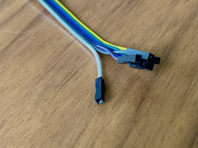
The pin header on the PinOne is ideal for connecting a female connector from the ribbon wire.
If the other end of your ribbon wire has a male connector, you can simply clamp this pin into the terminal strip by tightening a screw down onto it.
If the other end of the ribbon wire is female I found it easy enough to remove the plastic housing on the end of the wire. With an X-Acto knife blade, scalpel, or needle-nose tweezers you can bend the small black tab up from the center of the housing.
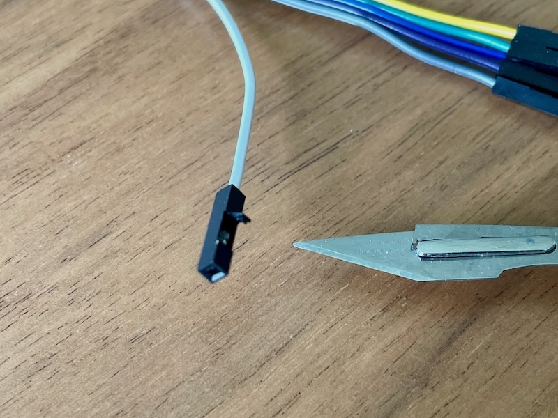
Then slip the plastic housing off. The metal crimped end that is left can easily be sandwiched under the a terminal strip screw.
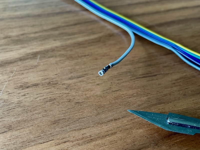
The 20cm (8") ribbon cable should be long enough to connect the pins from the PinOne to the bus strips.
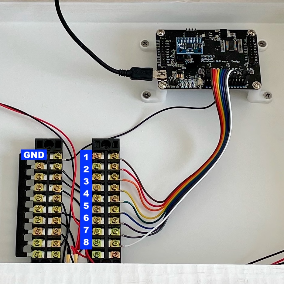
The photo above shows eight ribbon wires running from the input pins 1 to 8 on the PinOne to eight positions on the right-most terminal block. A ninth (black) wire runs from the GND pin of the PinOne to the top position of the left-most terminal block. With those connections, we can begin to wire the switches to the terminal blocks to complete the hardware of the Quarter-Cab (Phase I).
You know, there is an extra screw remaining on the right terminal strip. If you wanted to add an extra button for something like “Extra Ball” for example, you could easily modify your Quarter-Cab and add it. Decide where you want to put the button and drill a hole for it. You can use pin 9 from the PinOne for it. And while there are no more screws on the left (ground) terminal strip, you can combine your ground wire from your extra button with one of the other ground wires in the terminal strip.
Wiring the Switches
The last hardware-related step to complete Phase I of the Quarter-Cab is to wire the switches to the terminal strips. With this last bit of wiring, the PinOne can sense whether the switches are pressed or not, and, by way of USB, the PC (and Visual Pinball) will also know whether the switches are pressed.
For each button/switch in the cabinet, you are going to run a red and black wire from the button pins mentioned earlier and connect the red wire to the terminal strip on the right and the black wire to the terminal strip on the left.
You can wire whichever button you want to whichever screw on the terminal strips you want. But for simplicity, I am going to suggest you follow this pattern:
Terminal 1 to Left Flipper button
Terminal 2 to Right Flipper button
Terminal 3 to Left Magna-Save button
Terminal 4 to Right Magna-Save button
Terminal 5 to Start Game button
Terminal 6 to Coin button
Terminal 7 to Plunger button
Terminal 8 to Exit button
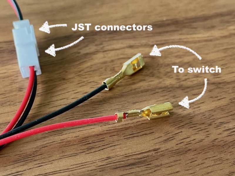
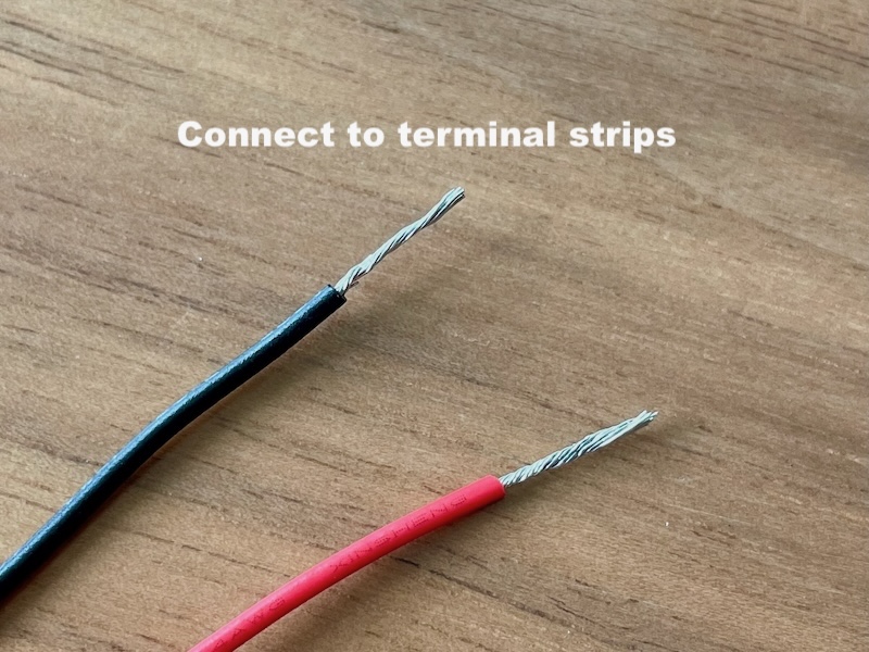
If you got the buttons from Cleveland Software Design, they should have come with wires that have leads suitable for connecting to the button itself. For buttons close to the terminal strips, like the coin button in the center on the front of the cabinet, you can cut off the JST connector (the white plastic connector) on the other end of the wires and then strip about 3/8" of the insulation off of both the black and red wire.
For buttons too far to reach with the wire, leave the JST connector on but attach one of the JST terminal button extension cables to get the additional length you need. You can then again cut off the last JST connector and strip the wires as you did before.
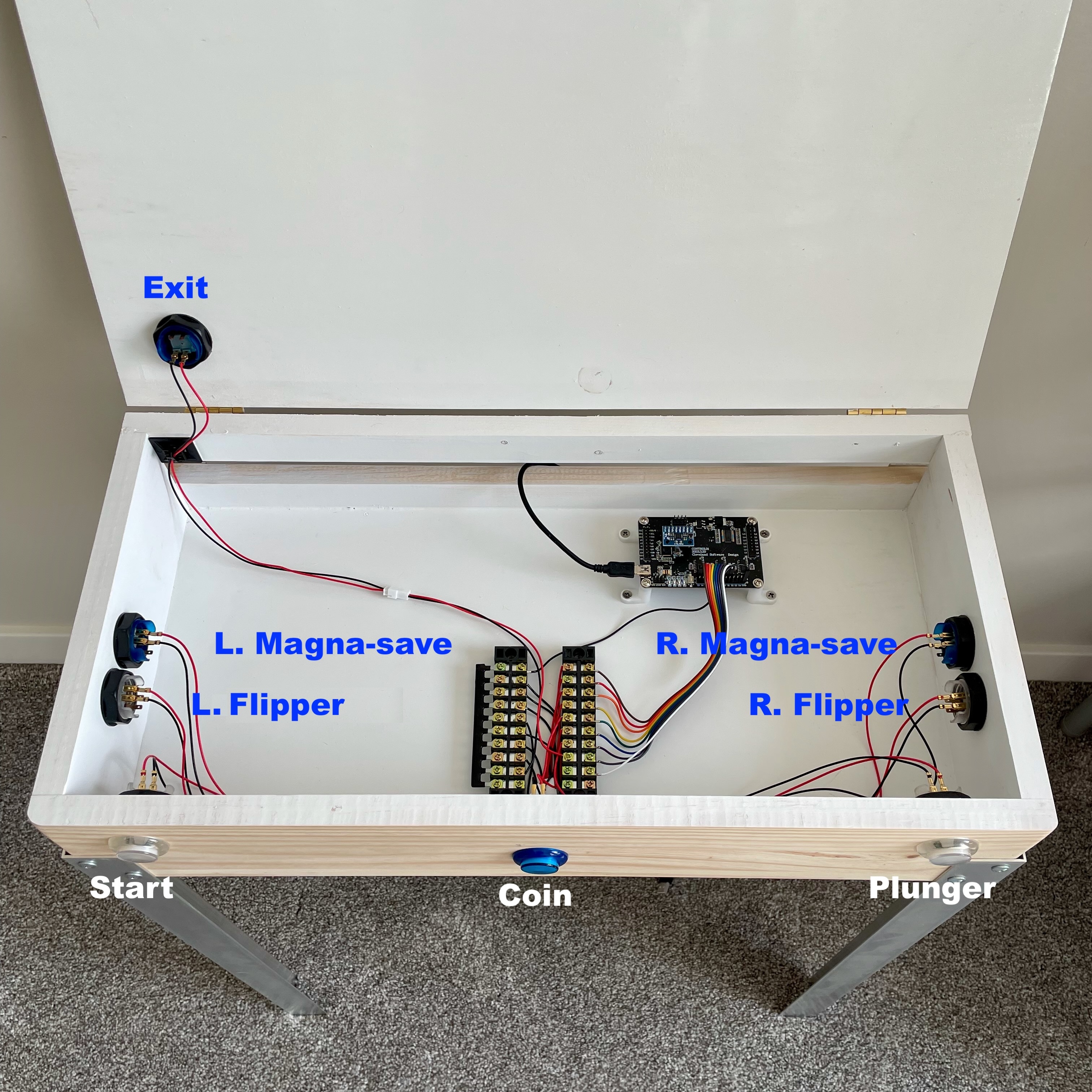
Above, all wired up and ready for configuration (software).
If I didn’t mention it before, there is no “polarity” to the switches so which pin gets a black wire and which pin gets a red wire is of no matter.
I routed the wires generally into the corners in the cabinet thereby leaving the middle still open for future upgrades (Phase II). You can pick up some adhesive backed wire anchors to secure the wires and keep them following around the inside edges of the cabinet.
Perhaps of particular note is how I wired the one button that is in the lid of the cabinet (top-left button in the image above) — the Exit button. Since I want the lid to be able to raise and lower, I made sure there was plenty of slack so the wire would still reach when the lid was completely open. I also ran the wire into the corner to keep it out of the way. I used one of the adhesive wire anchors to keep it positioned in the corner even as the lid is opened and closed.
Configuring
In order to use PinOne with your PC, there is a very basic configuration you have to do first. Start by downloading the PinOne config tool from Cleveland Software Design’s web page.
Connect a USB cable from the PinOne installed in your Quarter-Cab to the PC where you downloaded the software
above. Follow the instructions on the previous link.
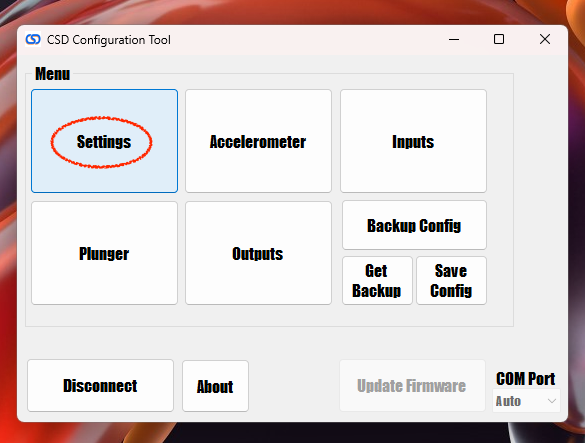
When you get to the above screen, the only thing we need to change is under
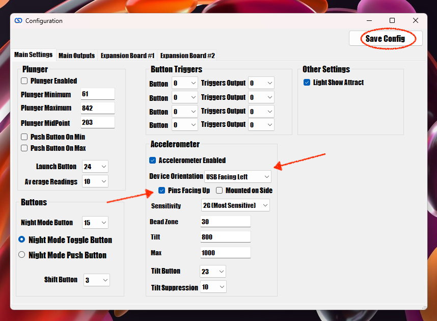
In the center of the
The final step is to configure Visual Pinball itself.
Launch VPX and without playing a table, go to the
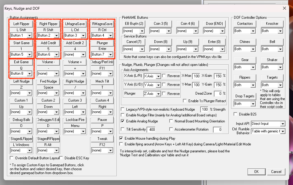
I have drawn boxes around the keys you need to configure. You just select the Button for each key as shown above. If you followed the wiring ordering I suggested earlier it’s basically 1, 2, 3, 4 ….
Completed & Phase II
That’s it. You should be able to simply open your favorite VPX pinball table now and play using your Quarter-Cab controller.
As the very first photo shows, I like to play seated and with the Quarter-Cab just low enough that my palms rest
more or less naturally on the corners of the cab like a real pinball table. I also leave the keyboard on top so
that I can hit
Don’t put your display on top — aggressive nudging could send it toppling.
Speaking of nudging, a simple way to test the nudge is to do so when the ball is first sitting in the plunger lane. There are settings in VPX for adjusting how sensitive the nudge response is. I suggest you play with that until you are happy.
If you want a standing posture, you might raise the Quarter-Cab up by adding four 2×2’s (perhaps about 12" long) as sort of extensions to the bottom end of the angle-aluminum legs. In fact by drilling a number of holes, you could even make it height-adjustable.
I’ll follow this post with what I am calling Phase II. I will add the hardware to build surround-sound feedback (SSF) into the Quarter-Cab. It promises to be much easier than Phase I since building the cabinet was the hardest part. But it will probably double the cost of the Quarter-Cab. If you push on and complete Phase II though, I think you will find that SSF takes virtual pinball to the next level of realism.
Enjoy.