Op-Amp Helper: Assembly
The Parts
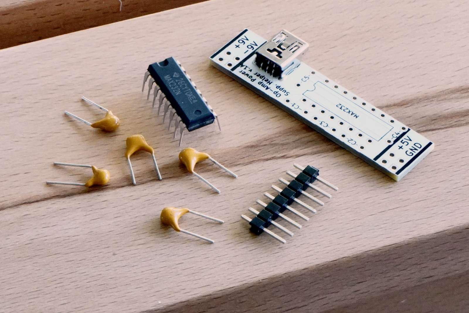
Assembly
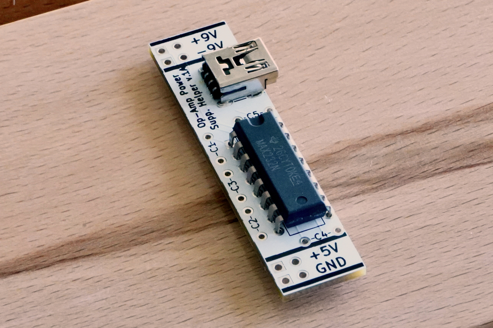
1) Generally you start by inserting and soldering the shortest components to the IC first. That would be the MAX232 IC.
It should be inserted from the top-side of the PCB (the side with the silkscreened image of the outline of the chip, the side with the USB connector).
There are two ways that the chip can be inserted. The silkscreen shows a notch at one end of the IC and there is a corresponding indentation (notch) on the physical MAX232 chip. This indicates which way to insert the IC.Carefully turn the PCB over and solder all 16 pins. You should trim the excess length of the pins off when the solder has cooled.
If wrestling the 16 pins of the chip into the holes in the PCB is a challenge, they sell special tools that make it a lot easier. Search for IC insertion tool.
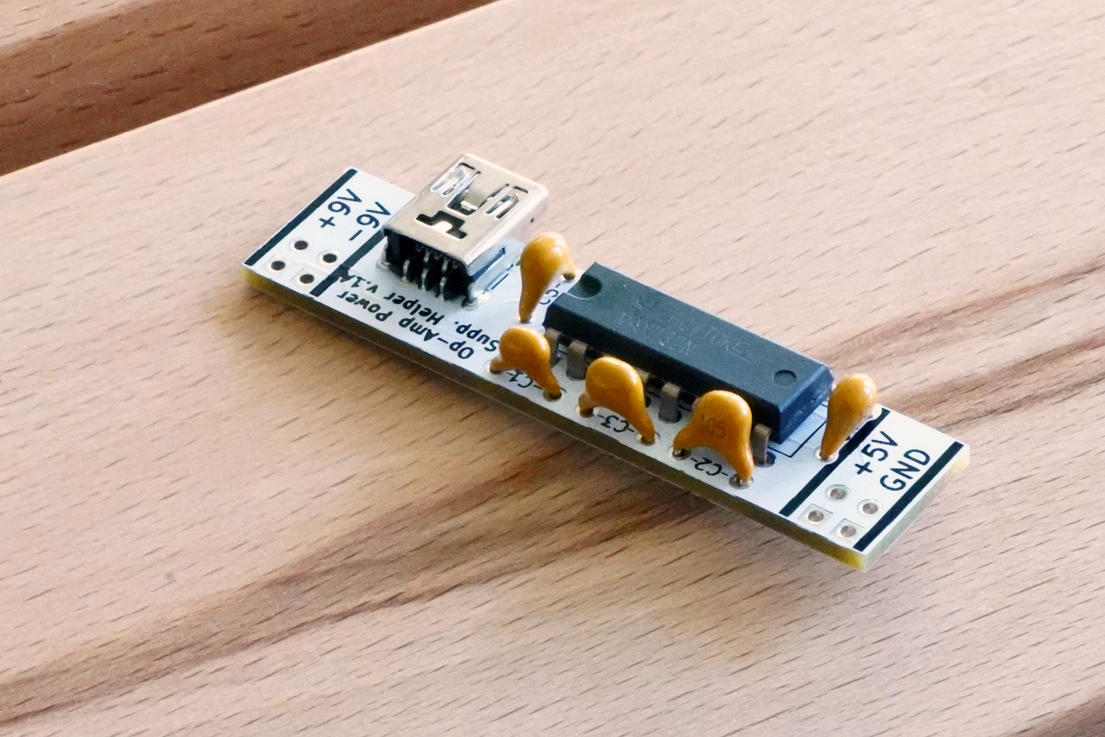
2) From the top-side of the PCB again, insert all 5 capacitors in the locations indicated on the PCB. Since these are not polarized capacitors (those with a positive and negative lead) it does not matter which way you insert them — I tend to insert them in a way that makes reading the value of the capacitor later easiest).
Bend the legs out a bit on the underside of the PCB such that you can turn the PCB over without the capacitors falling out. Solder all 10 legs. As before, trim the excess leads.
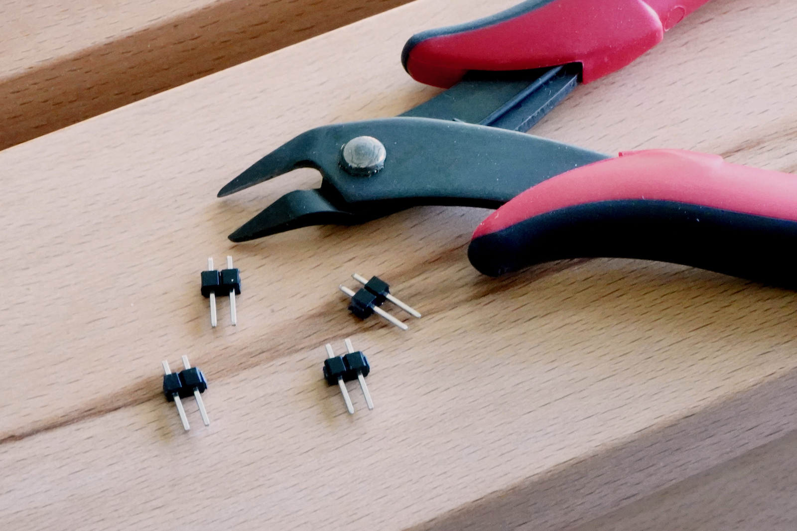
3) Lastly you’ll attach the header pins. The holes on each end of the PCB are for the pins. The holes are in pairs so you should use a pair of flush-cut pliers to clip off pairs of header.
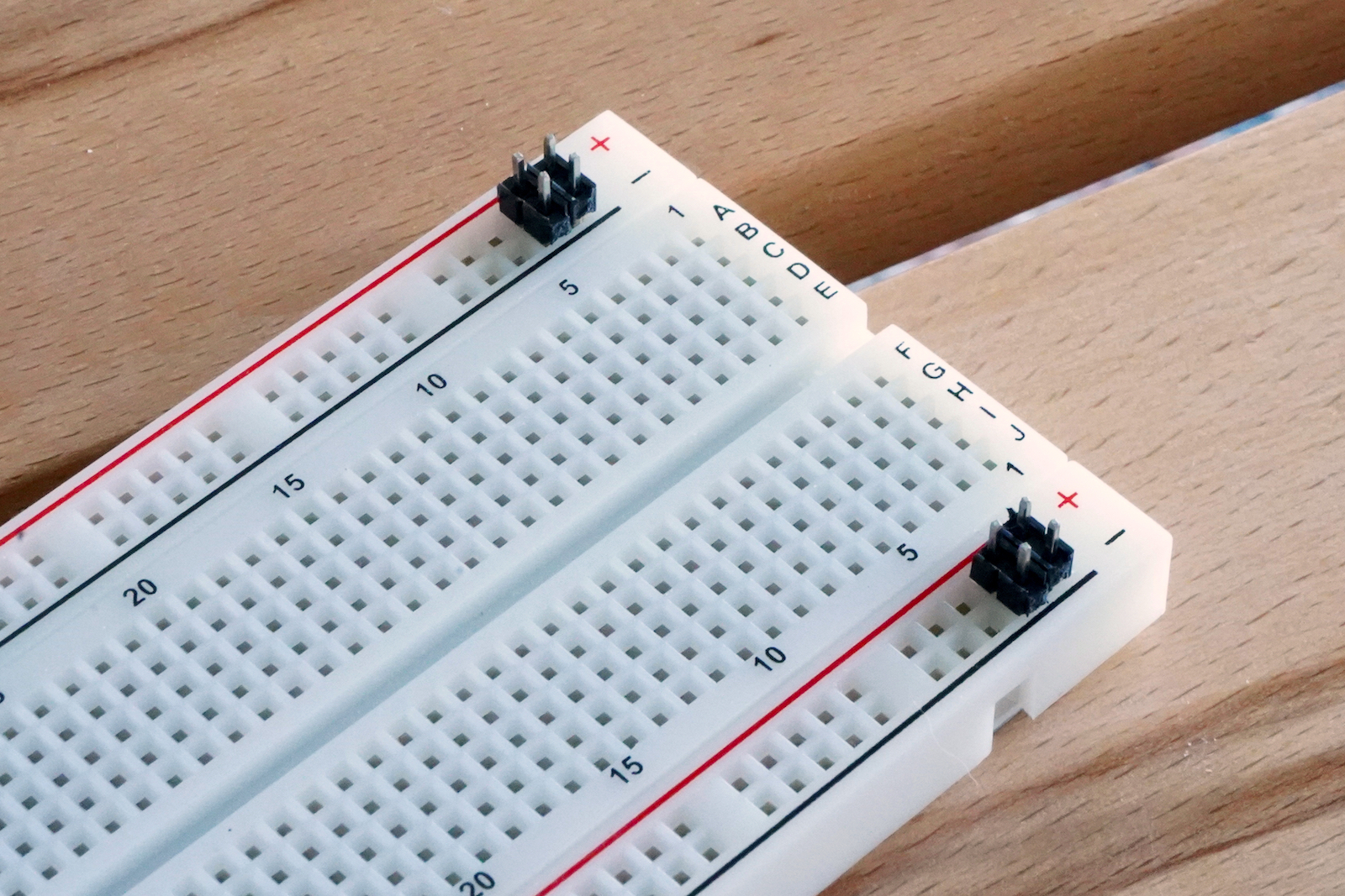
The best way to install the pins in the PCB is to have the breadboard handy that you intend to use with the finished board. You can then insert the long ends of the pin headers into the breadboard.
Put two pairs of pins in the top pair of power rails of the breadboard — in the right-most position. Make sure the long pins of the header go down into the breadboard. Then place the other pair of header pins in the bottom pair of power rails of the breadboard. You should be able to then easily place the PCB down on top of these pin headers lining up the corresponding holes.
Unfortunately the PCB is not balanced on the pin headers and so may require a third hand or a piece of tape to hold it level — parallel to the breadboard surface. You will want it level when you solder the pins of the headers.
You’ll solder all the header pins from the top-side of the PCB.
Another trick to help keep the PCB level (if you don’t have a third hand), is to do your best to keep it level and solder just a single header pin. You can then set the solder down and will now have a free hand. You can re-melt the soldered pin and use your free hand to now press the PCB down level with the breadboard. After you are happy with it you can easily solder the remaining pins as the first one will hold the PCB in the same position.
You can trim the excess again from the header pins that protrude through the top of the PCB.
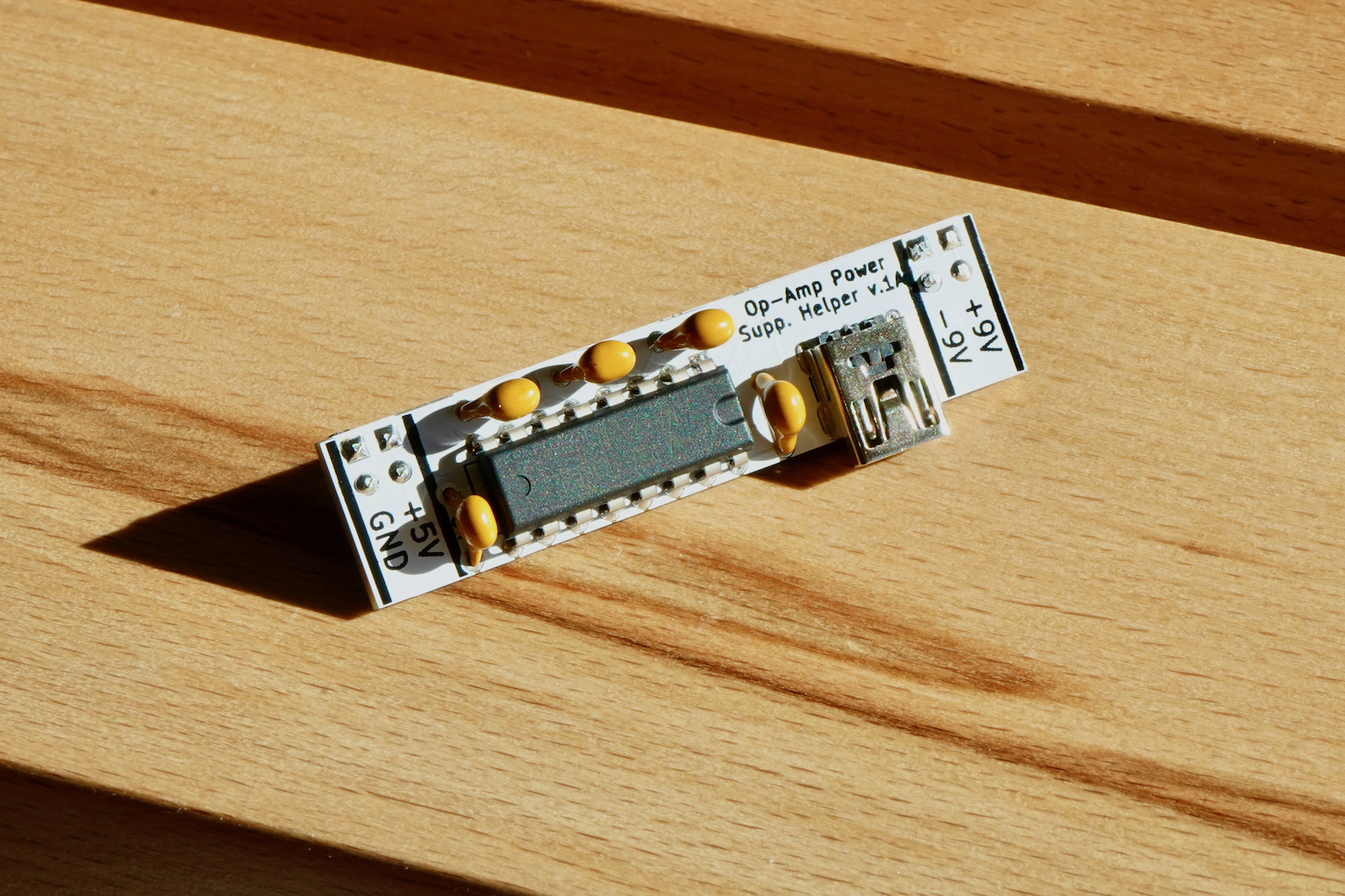
Your board is now done. Plug a Micro-USB cable into any suitable USB power supply and plug the Micro-USB end into the PCB. You should now have Ground and 5V on the bottom power rails of the breadboard and positive and negative 9 volts in the top pair of power rails.
If the solder flux bothers you (I confess, the white circuit boards look cool but show the flux a lot more than traditional green PCBs), the best way to clean it off that I have found is to use an old toothbrush and rubbing alcohol (isopropyl alcohol, often abbreviated IPA).